Fechter's Throttle Interface for RC controllers

fechter

Administrator
Staff member
Joined
Dec 31, 2006
Messages
16,565
Location
California Bay Area, USA
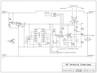
OK, since there seemed to be a need for such a thing and there does not appear to be any commercially available units, I designed a throttle interface for RC controllers. This allows you to use a regular bike throttle with a controller made for radio control.

This will work with both a standard hall effect or 5k resistor throttle.

It has an adjustable current limiter based on the Allegro ACS754 bidirectional hall current sensor. The current limit will adjust from near zero to whatever the maximum current of the Allegro sensor is. They have 100 and 150 amp versions in stock at Digikey. If you don't want to use the current limiting feature, it can be left out, but I think it is essential for proper operation on a bike.

There is a tie-in for a battery LVC and brake switches to override the throttle and kill output.

There is a built-in BEC circuit with 100v maximum input voltage.

There is a provision for additional main capacitors to supplement the controller's stock units.

The pulse generator is based on a ICM7556 dual cmos timer that is configured for voltage control. An op amp comparator monitors the current and decreases the throttle when the current limit is reached.

This design has NOT been fully tested yet. Some tweaking of the loop response may be needed depending on the model of controller used with it.

Throttle Interface 1_2 schematic.jpg
 
:?: Can you choose either Battery Side limiting or Armature Side limiting?

Given that these RC motors produce so much power as to be able to rip a typical bike transmission to shreds it might be a good idea to allow Armature Side current limiting to smooth out the power delivery.

A constant torque is easier to design around than one that is highest at low rpm and drops as the rpm rises. People that would be using their RC motors with their gears don't need low end torque because the gears can provide that. (that's what the gears are for)

Geared RC motored ebikes are best to use Armature Side limiting...
 
yes thank you Richard indeed :D,
being as i need to buy a controller anyway i could send you a hv110 to test with if it helps the general cause? seems like the least i could do? but i dont want anyone to get uppity if they have a different controller and want that testing with the board? anyway offer is there, please dont blow it up :) lol

Cheers,

D
 
deecanio said:
yes thank you Richard indeed :D,
being as i need to buy a controller anyway i could send you a hv110 to test with if it helps the general cause? seems like the least i could do? D

Thanks for the offer, but I think shipping from the UK would be more that what a new one costs. :?

As long as the controller is made for a 'standard' 1ms to 2ms pulse width, it should work.

I'll try to find something around here to test with.

Safe, the shown schematic is for battery side only. It would be a fairly minor change to make it work on the motor phases, but the calibration would be different. Maybe on the next version I can work that in so it can be used either way.
 
We have the technology, now who is going to build it? :lol:

Fechter,
Perhaps I missed something, but why did you choose throttle values of 2.5 volt-3.5 volt?
Also, do you have a parts list, along with a grand total?

Thanks for preemptively seeing a need, and moments later fulfilling the demand.

I have a cheapo 80 amp ESC that I would be willing to send you in exchange for a free board. pm me I will send it today if you like.
 
Gary is working on a board layout right now.
I'm hoping this thing is simple enough that we can offer them fully built and tested.

No estimate on cost yet. The bare board will cost more than all the parts.

The control voltage values are just for reference. They are just what I got from testing. I did not choose them. These are the voltages on pin 11 of the chip and do not have relavance other than for troubleshooting. The input from the throttle is roughly .8v to 4.2v (typical hall throttle). It will also work with a 0 to 5v signal from a pot throttle.
 
fechter said:
Thanks for the offer, but I think shipping from the UK would be more that what a new one costs. :?

well im buying from castle creations, i thought they were your side of the pond? i'll check, anyway let me know if you change your mind, its not a problem.
By the way, sorry for this basic question, does the board negate the need for the servo tester alltogether? in basic terms what would connect to what with it?

cheers Richard,

D
 
deecanio said:
fechter said:
Thanks for the offer, but I think shipping from the UK would be more that what a new one costs. :?

well im buying from castle creations, i thought they were your side of the pond? i'll check, anyway let me know if you change your mind, its not a problem.
By the way, sorry for this basic question, does the board negate the need for the servo tester alltogether? in basic terms what would connect to what with it?

cheers Richard,

D

Well, if you want to buy a new one and have it shipped to me, that would be dandy.

Yes, this thing takes the place of a servo tester and allows you to use a regular bike throttle. It connects to the battery, your bike throttle (hall or pot), and connects to the servo input of the controller.
 
:shock: outstanding work,that makes things so much easier for me, pm me your address and i'll send out a hv110 for testing, try not to pop it now :lol: do we know the rough dimensions of the board?

Cheers,

D
 
:shock: :eek:

Absolutely outstanding!

Now it just needs to be built.

Fetcher, can I get one to test? It is winter here. But, I do not mind doing some testing anyway.

I think a completed, ready to run setup would be best. Many people are not good with soldering up a kit.

I am open to doing whatever I can to help you out in this. I have been wanting this for quite some time and all my sources are dragging their heels. :?

Matt

Oh, Hey, how sharp is the throttle rolloff? Ideally it roll off smoothly with a somewhat gradual slope, rather than a sharp cutoff.

Thoughts?
 
I should have the layout complete in time to turn in tomorrow. That's my plan, anyway. :)

I think this is simple enough that we ought to at least be able to offer this as a complete kit, if not fully assembled and tested.

-- Gary
 
fechter said:
Safe, the shown schematic is for battery side only. It would be a fairly minor change to make it work on the motor phases, but the calibration would be different. Maybe on the next version I can work that in so it can be used either way.
I'm a little unsure of what problems you are solving on this one for the battery side that the old versions couldn't already do. :?

Are you doing anything that directly interfaces with the phase wires of the RC motor?

(it does not look like it)

With the brushed version (which I plan to make a Version 2.0 eventually that resolves the old problems) it's really simple and just uses a comparator and a sensor. This seems to add a lot of new "stuff".

What's all the new stuff for?

Basically the throttle pulldown part is a universal thing and should not require any of these other features. Or is the LVC cutoff addition a feature that just needed adding?

-----------------------------------------

:arrow: My latest design uses:

1 voltage regulator (to get a clean non-conflicting power supply)

1 current sensor (to measure the current)

1 comparator (to know when to pulldown the throttle)

...and then some connective stuff. I'm going to skip all the variable resistor stuff because the precision of the factory parts (like the sensor) is rated as something like 1% so if I use the correct parts it should not need adjustment.
 
file.php


recumpence said:
The majority of the other "Stuff" is for the pulse width generation and modulation. :D
Is this actually "replacing" the ESC?

That would be cool... otherwise I don't really understand how these controllers (ESC) need a pulsed current... is that how they work?

The throttles I use have a simple voltage from 0 to about 4.5 volts.

------------------------------------------------

It appears that this circuit does your plain vanilla throttle pulldown but then adds the LVC and the PWM chip that does something I don't understand. What is the chip for?

Is the chip some how "digitizing" the throttle signal? For what reason I have no idea, but the plain vanilla style uses pure analog so this might be an improved approach. Maybe there is some reason to stabilize the throttle signal?

Hmmmmmm?

Do RC motor ESC's have problems with a comparator because their throttle signals oscillate too much?

So many questions... :?
 
This is a throttle, not an ESC. That would require a LOT more "Stuff". :wink:

RC ESCs are VERY high quality and high tech (the higher end ones, anyway). We just need to limit their current so they will live.

Matt
 
recumpence said:
This is a throttle, not an ESC. That would require a LOT more "Stuff". :wink: RC ESCs are VERY high quality and high tech (the higher end ones, anyway). We just need to limit their current so they will live.
It didn't look like it could replace the ESC. My basic curiosity (and I've been studying Fechters circuits for a while) is where he's going with this new design. What problems is he trying to solve?

The old design was very, very simple and I've got a way to potentially simplify it even more. (I'll be converting a Chinese controller to Armature Current Limiting)

The basic idea is to measure with a current sensor and then compare that to a baseline voltage. If the current sensor reads too high it pulls down the throttle. If not, the circuit does nothing and does not interfere.

--------------------------------------

It's possible that there is some major difference in RC motors ESC's that I'm totally unaware of... if so, I'd like to know what it is so that one day when I get around to building an RC motor bike I'll know what is going on. :)
 
Safe, RC controllers are designed to run off a signal from a radio control receiver. The throttle signal to the controller is a pulse that varies from 1ms at zero throttle to to 2ms at full throttle. My circuit simulates the output of a RC receiver based on the input from a standard bike throttle and has the current limiting feature. I'll post a variation that would work for motor current limiting.

Not sure about the size yet. The biggest parts will be the power supply capacitors.
I'm thinking it will be roughly 2" x 3" or so. I'm still not exactly sure how many capacitors we need to protect the controller either. Some of the RC forum guys are adding quite a few, but I think it may be overkill. It also depends on how close you are to the maximum voltage rating of the controller.
 
MitchJi said:
Hi D,

deecanio said:
well i'm buying from castle creations.

D

John Holmes has it for less ($224.99 - $40.50 discount = $184.49):
http://holmeshobbies.com/product.php?productid=247&cat=2&page=1

Subtotal: $224.99
Discount coupon Unset Coupon : $40.50
Discounted subtotal: $184.49

Use the code "esc" to get the Coupon Discount.


Hi All,

Again thanks Mitch, that more or less covers postage, i'll pop it on my parts thread so JRH gets more orders.
One hv110 from john rob's site on it's way to you Mr Fechter :lol: and Again thank you for doing this for us.
PM me your address and we'll get the testing under way!!!!

**edit** just received, placing order now :)

**EDIT** jrb site sais out of stock?? i'll drop him a PM and see whats going on, if he doesnt have them and won't for a while i'll send it from castle, nice to keep it in the forum tho if possible.


Cheers,


D
 
So cool, Thanks D!

It's not so often that I actually get anything for my work.


Now, to keep Safe happy, below is how you would modify the circuit for phase current limiting on a brushless motor. The current sensor can go either way in the phase wire since it's AC.
There are a few guesses for component values that may need refining after testing. Diode D3 picks off the peaks of the positive currents and pumps up a capacitor to roughly follow the peak current.

With a brushed motor, you could just use the previous design and move the sensor.
 

Attachments

  • RC throttle interface motor current.jpg
    RC throttle interface motor current.jpg
    42 KB · Views: 6,599
Hi D,

deecanio said:
Hi All,

**EDIT** jrb site sais out of stock?? i'll drop him a PM and see whats going on, if he doesnt have them and won't for a while i'll send it from castle, nice to keep it in the forum tho if possible.

Cheers,

D

Castle doesn't offer a very good price ($337 for less than 10):
http://www.castlespecialprojects.com/csp_50_volts.html

Phoenix HV-110 Price < 10 units $337.44

Phoenix HV-110Price > 10 units $269.95

Google (shopping there is one listing for $209 and several for about $230):
http://www.google.com/products?q=Phoenix+HV-110&btnG=Search+Products&hl=en
 
fechter said:
So cool, Thanks D!

It's not so often that I actually get anything for my work.

Hi Richard,

:shock: hehehehe,I hope that i haven't given you the wrong impression Richard - i will need the HV back at some point to go on my bike :lol: :lol: :lol:
But im totally happy to have you use it for testing no problem at all, i'll give John a day or so to get back to me on the pm and if i dont hear by Saturday night i'll order from castle and ship straight to you.
I think once we get this board tested the community will owe you and Gary a debt of thanks at least, maybe we could club together and get you one for yourself, i'd happily contribute? anyway test hv on the way :lol:


Cheers,

D
 
Back
Top