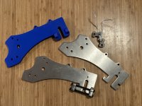
torque arm picture thread

Comrade said:
That's a much simpler design for sure. I'd beef up the "hooks" a little, maybe 50%.

Given the change to 3/8" material, though, I've no real way to determine if it'd truly make a difference. But it's no big deal to beef it out either (aside from needing a longer bolt), so sure.

Comrade said:
And remove superfluous metal from the perpendicular bolt plates. All that overhang that's not under the bolt heads isn't really doing anything.

Incorrect -- it's doing the very important job of being prettier :lol: I also like that it causes the plate to be self centering, so even if I were to reduce it I'd want to keep some of lip edge. A part of it is also the place I want to get it made has some minimum size requirements that this piece gets very close to, so a little extra material size ensures smooth production.
 
One issue that I have been running into with my clamping torque arms (made a few years ago) is that my fitment was a little bit off so when I cranked the bolt down it bent the torque arm a bit and when I loosened it the metal didn't rebound far enough to easily to get the wheel back out.
For my next revision I plan to be more precise on the tolerances and also try to implement a way to slightly spread the torque arm so that I can slide the axle out.
 
chuyskywalker said:
the place I want to get it made has some minimum size requirements that this piece gets very close to, so a little extra material size ensures smooth production.

Hint: I always join small and not so small parts through a little connector. The parts can be broken apart by hand and the little connector is gone in seconds on a belt sander. It saves on costs too. Most parts are priced for the time they take to pick up, inspect and track with the order. If you join 10 parts together those costs will be calculated as for 1 part, while materials and laser time will be identical to cutting 10 pieces separately.
 
captain387 said:
One issue that I have been running into with my clamping torque arms (made a few years ago) is that my fitment was a little bit off so when I cranked the bolt down it bent the torque arm a bit and when I loosened it the metal didn't rebound far enough to easily to get the wheel back out.
For my next revision I plan to be more precise on the tolerances and also try to implement a way to slightly spread the torque arm so that I can slide the axle out.
This is why a 2-part TA works better. 1/4” grade 8 bolts will work fine.

If you want precision in a higher thickness with laser cutting you can get them cut from 3/16, stack and weld together, then drill clamping holes. A laser doesn’t cut perfectly straight the thicker the material. In 1/4 stainless it is as much as .003” per side.
 
Well, they are not going to break. :lol: Maybe next iteration can be aluminum with steel inserts where it matters.
 
What about the idea of welding a torque arm to the axle to bypass the flat entirely?

The protruding axle would need to be long enough to mount a nut with space to loosen the nut enough to drop the wheel out of the frame dropouts and then weld the torque arm outboard of that, and the torque arm mount to the frame would need to be released to accommodate tire changes.

Disassemble the motor to determine which side is best for a dedicated welded arm (that doesn't interfere with assembly/disassembly). Remember to install the nut/washer when re-installing the axle to the motor.

I'll admit I think that a high-powered motor that relies on axle flats is very poor engineering - so replacing the axle with a longer one isn't out of scope. For myself, I'll just buy motors with dedicated torque arm mounting.
 
The protruding axle would need to be long enough to mount a nut with space to loosen the nut enough to drop the wheel out of the frame dropouts and then weld the torque arm outboard of that, and the torque arm mount to the frame would need to be released to accommodate tire changes

Or the torque arm could be like the Grin All Axle or GMAC "integrated" arm is, mounted to the inboard side of the dropout (at the axle shoulder. In this case the arm would be welded to the shoulder of the axle, and would be more effective / less likely to shear the axle off, because the torque would be transferred before it reaches hte axle proper, so the axle would hten only be used to secure the wheel in the dropouts (which is all it's really good for anyway if you have a system with sufficiently high torque ;) ).

It would take the place of whatever washer you would have used on that side inboard of the dropouts.

The torque arm doesn't have to be all that thick if it's welded to the axle, just enough to not be able to deform under load, and the longer the arm is (and the more secured-to-frame area it has) the better it will transfer the load to the frame
 
mounted to the inboard side of the dropout
Yes, probably better.

Custom, but then anything else in this situation is as well. I think this is better.
 
This is apparently a new offering from Grin Tech that (IMHO) cleverly addresses several important issues (axle pinch-clamping, sufficient TA thickness and material strength, arm length, clocking options) :

V7 Regen Torque Arm


ta-torqarm_v7_wsplineclamp.jpg
 
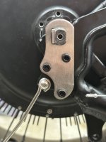
I actually took a bit of inspiration from the Grin V7 (because, at the time, it was only available for 12mm axles, now there's a 14mm version), but I had a chonker 16mm axle on this motor. Mocked up a plate that would secure to existing bolt holes on my RadMini4 and sent the CAD design off to PCBWay to get them to CNC machine it up. (The front on 2d is simple enough, but it also needs two M5 threaded holes rather precisely drilled+tapped on the side.)

2023-07-21 17.30.49.jpg

Above you can see how this bolts on and has a small space for a piece of metal to be compressed on to the axel from the side via 2 M5 bolts.

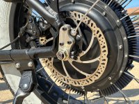
When fully installed it looks like this:

2023-09-04 10.12.39.jpg

So far I've got about 100 miles on it and recently had to change the tire (massive piece of thin sheet metal straight through the tire, liner, and tube -- no stopping that) and could see ZERO wear on the axle nor the typical "rocking motion is creating thread marks" on the torque arm or dropouts. And I have this thing set for HEAVY regen (I think, like, 40-60A).

Very happy with how it turned out.
 
I actually took a bit of inspiration from the Grin V7 (because, at the time, it was only available for 12mm axles, now there's a 14mm version), but I had a chonker 16mm axle on this motor. Mocked up a plate that would secure to existing bolt holes on my RadMini4 and sent the CAD design off to PCBWay to get them to CNC machine it up. (The front on 2d is simple enough, but it also needs two M5 threaded holes rather precisely drilled+tapped on the side.)

View attachment 340363

Above you can see how this bolts on and has a small space for a piece of metal to be compressed on to the axel from the side via 2 M5 bolts.

When fully installed it looks like this:

View attachment 340364

So far I've got about 100 miles on it and recently had to change the tire (massive piece of thin sheet metal straight through the tire, liner, and tube -- no stopping that) and could see ZERO wear on the axle nor the typical "rocking motion is creating thread marks" on the torque arm or dropouts. And I have this thing set for HEAVY regen (I think, like, 40-60A).

Very happy with how it turned out.
Frick yeah!
 
I wish I had the tools to steal your design for the SB Cruiser's dropouts. :) (I mostly do but I am not sure my HF drill press can drill thru the metal I have available...I will probably find out though, when I get around to making new dropouts).
 
I wish I had the tools to steal your design for the SB Cruiser's dropouts. :) (I mostly do but I am not sure my HF drill press can drill thru the metal I have available...I will probably find out though, when I get around to making new dropouts).
I originally got the first one from sendcutsend for, pretty cheap -- but then snapped a tap after trying to drill the holes in the side (since SCS only does the main 2d profile laser cut).

PCBWay was (checking...) $74 for it to be fully milled, drilled, tapped, and shipped.

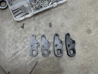
All the first iterations were done in Fusion360 and 3d printed for fitment/testing.

2023-07-12 19.17.13.jpg

Took about 4 tries to get all the holes lined up juuuuust right.

There's more info on my blog about the design of the clamp and the final piece
 
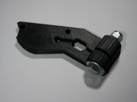
I have been running my 3D printed dropout for some thousands of miles on my full suspension bike. 5000+ miles at this point.

If the idea of a plastic dropout is an issue to you, take your final 3D print to a local machine shop and have them reproduce it in steel.

If you are wondering what mine looks like, look at the image next to my e-beach name. Kinda hard to see but it has been there for couple of years at least. It is also specific to my bike so this one is not universal.

:)
⚡
That's nuts. I would never have though it would hold up being 3D printed. I'm assuming 100% infill. What filament did you use? Surely this would not work with regular PLA.

Cheers
 
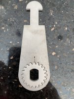
I bought some cheap adjustable torque arms from aliexpress and am pretty disappointed- they are loose as a goose with huge amounts of play in the teeth and the axle slot. I will attempt to shim the axles and epoxy the teeth but it’s a bandaid. Luckily they are on a thick steel fork of a factory e-bike, so it doesn’t really need them anyway.
 

Attachments

  • IMG_0058.jpeg
    IMG_0058.jpeg
    2.1 MB · Views: 15
Instead of epoxy … a few whacks on each side with a mallet, followed by a little filing.

I can’t say I’ve done this to torque arms, but it will work. I do it regularly to extend the life of homemade cone spanners.
 
That's nuts. I would never have though it would hold up being 3D printed. I'm assuming 100% infill. What filament did you use? Surely this would not work with regular PLA.

Cheers
Yes PLA. Yes 100% infill.

Statement: One man's experiment does not guarantee safety. ;)

Caveats: 36v and 48 volt systems. I started with 36v and went to 48v later.

Batteries: Headway LiFePO4 which are low C upon startup. Low torque on startup.

Flat or gradual hills in my riding area. 10% or 12% grades are short.

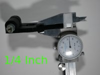
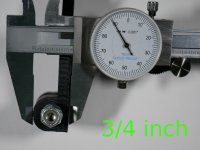
I am of the opinion that 3D printed plastics are a viable option for e-bike torque arms depending on the e-bike system. The axle nut and the torque arm bolt do a lot to stop any movement of the axle. The axle embeds itself into the plastic as does the lock washers. Again, One man's experiment does not guarantee safety....

:)
⚡
 

Attachments

  • 1 quarter inch.JPG
    1 quarter inch.JPG
    5.9 MB · Views: 11
  • 3 quarter inch.JPG
    3 quarter inch.JPG
    6.3 MB · Views: 11
  • plastic torque arm.JPG
    plastic torque arm.JPG
    5.1 MB · Views: 12
Last edited:
more then 5000 miles on it.....weather you like it or not! :mrgreen:

:)
⚡
Keep the axle nuts tight, and stay on good terms with the bitch goddess of e-bikes.

I've seen too many steel torque arms with axle threads sliced through their former flats to try anything weaker than mild steel. But results speak louder than guesses, so whatever works....
 
Back
Top