ZapPat
10 kW
Camlight is right, since we already see this SOA problem with the FETs in the original CBA. If you really want something that'll eat up lots of current without a problem (like hotspots developping in your linear biased FET), just use the FET as a switcher as it is designed for.
Of course, by using the FETs as a switch, it obviously won't be dissipating much heat anymore. You would have to find yourself some real chunky heatsink-mountable resistors to put on that huge aluminum heatsink, plus an appropriate inductor (coil) and capacitors to filter the FET output going to the resistors. There would have to be some kind of current feedback from a shunt to control the FET's duty cycle. This may sound complicated, but even the very simple brushed DC motor controllers work this way once they hit their current limited operating zone.
For this load solution one would basicaly need:
1 FET + 1 diode + small heatsink (or multiples for really high currents)
1 Shunt (for current feedback)
PWM controller (could be a specialized IC or use a microcontroller)
Inductor + capacitors (to filter FET switcher output)
Large heatsink such as Rick or Doc have posted here
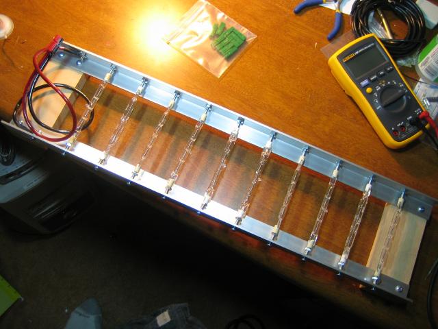
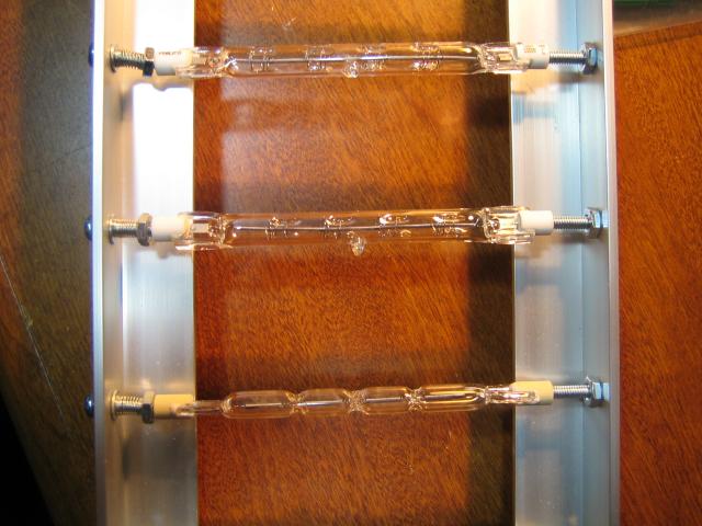
Heatsink mountable load resistors such as these:
View attachment 50W power resistors - small.jpg
I'm more of a digital-type guy, so this is my non-linear way of seeing this solution. I'm sure there are simple to use IC's out there that could be the brains of this circuit, but one could also write a fairly simple and small MCU program to do this in a customizable way. Another advantage of not using the FETs themselves as the load is that we can change the power resistor hookup quite easily since it is external to the PWM regulator circuit.
Of course, by using the FETs as a switch, it obviously won't be dissipating much heat anymore. You would have to find yourself some real chunky heatsink-mountable resistors to put on that huge aluminum heatsink, plus an appropriate inductor (coil) and capacitors to filter the FET output going to the resistors. There would have to be some kind of current feedback from a shunt to control the FET's duty cycle. This may sound complicated, but even the very simple brushed DC motor controllers work this way once they hit their current limited operating zone.
For this load solution one would basicaly need:
1 FET + 1 diode + small heatsink (or multiples for really high currents)
1 Shunt (for current feedback)
PWM controller (could be a specialized IC or use a microcontroller)
Inductor + capacitors (to filter FET switcher output)
Large heatsink such as Rick or Doc have posted here
Heatsink mountable load resistors such as these:
View attachment 50W power resistors - small.jpg
I'm more of a digital-type guy, so this is my non-linear way of seeing this solution. I'm sure there are simple to use IC's out there that could be the brains of this circuit, but one could also write a fairly simple and small MCU program to do this in a customizable way. Another advantage of not using the FETs themselves as the load is that we can change the power resistor hookup quite easily since it is external to the PWM regulator circuit.
 - -|
- -|