100WV 50A max 500W Active Load

OK, the linear principal is simple enough I can see now. So everything to the right of the amp adjust pot (aka voltage reference) will be repeated for each FET used, is this right?

So one of the PIC's would be used as the voltage reference instead of much of the left part of the circuit, is this the idea?

Well, I think I'll do like John suggested and start to draw up what a switched cell analyser/load would look like. My problem is trying to keep out cool feature ideas when I work on a project... :roll: If it works out, Doc will be able to pump at least 100A out of small module, and into any homebrew load of appropriate resistive value. I think I have some good low voltage FETs to start out with and all the other parts I would need too. And I won't go layout crazy like I do with my controller, and instead slow down switching speed a bit to make designing the PCB simpler. And 5V will be much easier than the ~65V I'm used of, so this also should help.

As for PICs, I'm looking into which one to use, but I remember that there is one with SMPS (switching mode power supply) oriented peripherals.

I'll post when I've worked out the basic feature set and maybe a gross schematic too.

Let the linear vs digital showdown commence! :twisted: :wink:

Pat
 
yes, basically the PIC would provide the voltage reference.

it would also provide a signal for current limiting to keep the Fet in the SOA. so i guess it would also need to read a scaled value of the load voltage and then limit the current to a safe region regardless of the value on the pot. a couple of LED's to show if the current limit has been exceeded or not would be nice as well.

rick
 
Excellent Pat! I'm really looking forward to seeing how a switching design will work. I think I have a grasp on the basics, but it's always great to be shown a circuit by someone who knows a lot more than i do about it. Let slip the load design dogs of war! :D :D

I think you're right about those motor/SMPS/PWM feature-rich PICs...good luck with the search.

I'll work up a schematic later this week with my approach for a linear design. I'll be taking the basic design for the predecessor of the CC-400 and pulling off some extra goodies to bring the price wayyyy down. I've worked up a few pages of notes for the feature set and my initial design will probably have the option for several different features. Things like using a pot for current control or adding a DAC to the PIC and using that (via jumpers, a pot, serial port command, etc.) to set the current level. I'm hoping, without making the board too big, to give users the option of adding features by adding a jumper and soldering in additional components (over the base circuit).

We'll see how that works though. Like you, I tend to want to throw everything in the first time around. :mrgreen:
 
well i did a little more hunting on the availability of these Fairchild FETs. good news for anyone interested in building a load living in the UK. Farnell stocks most of them. bad news for North America. Newark is Farnell's partner here. if we buy them not only do we get to pay the regular shipping and handling, but we also get to pay an additional $20.00 for Farnell to ship to Newark. ouch that hurts. attached is a spreadsheet with the current availability

so for us in North America our options seem to be:
FDA69N25 - Digi-Key $4.65USD
FDA59N25 - Mouser $5.54USD
FDA59N30 - Future $3.10CAD 13k pcs in route should be stock in 5-10 days.
FDA33N25 - Mouser $1.32USD
FDA33N25 - Digikey $1.65USD

Arrow has somme decent pricces on the FDA62N28 and FDA79N15. but these are non-stock, 3week lead time, $50.00USD minimum order. i have never dealt with Arrow. so i don't know.

for a Canadian, the FDA59N30 at $3.10CAD seems like the best choice financially. but will it work. in comparison the original suggestion of the FDA69N25 works out to $6.27CAD. is it worth the difference?

any suggestions?

rick
 

Attachments

  • fet availability- 20090312.xls
    21 KB · Views: 136
Nice catch Doc!
I'll translate the article and take a peek. Seems to be a pretty complex circuit and would be a tough home-build. but, as you said, it might give us some good design ideas.

I'm very interested to see what testing methodology they use. It's tough to pick one when you have some cells being drained by motor controllers at very high frequencies but the IR tests are typically at DC (multiple current levels) or 1kHz. Not sure how the results translate to EV speed controller use.

But, this means more to learn and that's always a good thing. :mrgreen:
 
rkosiorek said:
Arrow has somme decent pricces on the FDA62N28 and FDA79N15. but these are non-stock, 3week lead time, $50.00USD minimum order. i have never dealt with Arrow. so i don't know.

for a Canadian, the FDA59N30 at $3.10CAD seems like the best choice financially. but will it work. in comparison the original suggestion of the FDA69N25 works out to $6.27CAD. is it worth the difference?

any suggestions?

rick
Rick,
Arrow has been utterly reliable as a supplier for me over the past 5 years. I would trust them for any major buy.

While the 69N25 is more expensive, the final cost difference might be minimal when everything is taken into account. I'll take a peek at the data sheets and post here. It wouldn't take much of a difference in the thermal resistance or SOA specs to make the more expensive FET actually less expensive to use is it meant we could use smaller heat sinks or have a higher power rating. :D
 
rkosiorek said:
for a Canadian, the FDA59N30 at $3.10CAD seems like the best choice financially. but will it work. in comparison the original suggestion of the FDA69N25 works out to $6.27CAD. is it worth the difference?

any suggestions?

rick
I took a look at the data sheets and the FDA59N30 seems to be the better choice to start with.
Calculating the on-state resistance when hot, here are the current levels they can pass and my recommendations for rating each one in a load design:
FDA59N30 = 17A @ 2.0V when hot, rate for 13A. Could be as low as 10A depending on PCB and wiring.
FDA69N25 = 24A @ 2.0V when hot, rate for 20A. Could be as low as 15A depending on PCB and wiring.

Both can handle about 20A up to 20V and about 10A up to 45V...assuming monster cooling, that is. :mrgreen:
And they have close to identical thermal resistance, voltage, and power ratings (in terms of what's important for our load), so either is OK.

Bottom line: The FDA69N25 can be conservatively rated at 15A for single-cell discharging and the FDA59N30 can be conservatively rated at 10A. Since we're limited by the heat sink and fan's ability to remove the heat, I'm not sure whether being able to go to 15A is worth the extra cost of the FDA69N25. It could very well be the case, I haven't done the numbers yet and priced out the parts needed. I say go with your choice, the FDA59N30 to save some $$$ with any prototype you work up. We can always drop in FDA69N25's to up the current ratings if the cooling can handle the additional power or if the user is only doing low-voltage discharges and needs to take advantage of the extra 5A+ capability of the FDA69N25 near LVC for a single cell.
 
Doctorbass said:
Guys.. I found an intersting RI tester for RC... on RCgroup.. the PDF also have the SCHEMATIC !!!!
this is the RIM-1000... (german article)
http://www.elektromodellflug.de/Uploads/rim2003_V3.pdf
that may give us idea about the desing for RI testing!

Doc
I had Google translate the text (attached). I tried to export the images to include with the Word file but Acrobat could only extract some of the graphics, just the photos. Wasn't worth increasing the file size just for that.

I divided the translated text into paragraphs as best as I could but couldn't determine the break for a couple of them. As you can guess, reading raw Google-translated text is a challenge :roll: but we should be able to get an idea as to how the meter was designed. Except for those of you who can speak German, of course. :mrgreen:
 

Attachments

  • Battery IR Meter RIM 1000 English Translation.doc
    52.4 KB · Views: 198
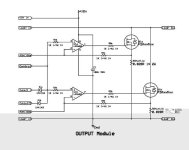
so here is a quick schematic of the output section. i chose to set it up for 2 FETs per module.

i decided to use an LMC6082 precision op amp as it is the only one with decent specs that is affordable and still comes in a DIP package. also it is a true rail to rail amp so it does not need a - supply rail.

Modular load.jpg

the "Control" input is the voltage used to adjust the current. with the design it would be 10mV per amp. so for a 10A load the input "control" would be 0.10V.

the "MONITORa" and MONITORb" can be used to read the voltage across the individual shunts.

the "CUTOFFa" and CUTOFFb" inputs can be used to turn the unit off by connecting either one to ground.

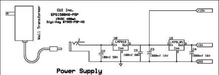
the pdf version also includes a power supply.

rick
 

Attachments

  • Modular load.pdf
    15.6 KB · Views: 270
Great start Rick!
A couple of observations, please pardon me for just jumping in and listing them...
- I would recommend a 0.01uF cap from each op-amp's output to the inverting input. This slows down the servo loop and helps to prevent oscillations. The bandwidth is still plenty wide enough to handle any of our loop response-time needs.
- I think that the current sense resistor should be rated 5W or higher. At 10A, each resistor is dissipating 2W and that will cause a lot of drift with a 2W resistor. The life expectancy of the resistor at 100% load is only about 1,000hrs too, typically.
- I may be wrong but wouldn't pulling the Cutoff1 or Cutoff2 input to GND leave the op-amp's inverting inputs at 0.7V (or so) above GND because of the diode's voltage drop? You could reverse the diodes and connect them to the non-inverting inputs. Then, bringing the Cutoff1 or 2 inputs high would cause the servo loops to think that there's too much current flowing and the op-amp outputs would go down to within a few millivolts of zero volts.
- The LMC6082 looks terrific. I've used the LT1013 precision op-amp with much success when controlling loads and, I think, it's less expensive than the LMC6082. The LMC6082 would certainly work though and the pinouts for both op-amp's DIP packages are the same. The pinouts are NOT the same for the SOIC packages though! Just wanted to mention that in case anyone is considering going surface-mount with these. :)
 
CamLight said:
I'm very interested to see what testing methodology they use. It's tough to pick one when you have some cells being drained by motor controllers at very high frequencies but the IR tests are typically at DC (multiple current levels) or 1kHz. Not sure how the results translate to EV speed controller use.
I've often wondered about this myself, what would be most representative of EV use? I think Doc wants the Internal Resistance test done multiple times through discharge, which will be easy to do using current pulses of at least two different strengths (maybe more), and measuring the voltage level variations. Different statistics could then be given after the PC analyses the data, depending on what we want to know.

As for how a battery sees a controller: If the controller has adequate input capacitance (as it should) to avoid ripple-related problems, the battery pack is seeing mostly a DC load. This load changes with the controller's current use of course. There will be a small amount of AC ripple also at the controller's input which is dependant on the load current, controller capacitance and battery wiring inductance. The battery pack itself will see less ripple than the controller's input, since the battery wire's inductance isolates it partially from any ripple that may be present at the controller's input. This being said, having sufficient capacitance at the controller's input will make it look like a DC load to the battery (I know Doc is concerned about this point).

While I was musing over the use of a PWM vs a linear load for testing, I had an idea that might just work out very well. I've been working on my own controller for a long while already, and it occured to me that a controller has almost everything needed to do what I want. I might add a small amount of additionnal filtering at the input if needed to remove any AC ripple that the cell/battery might see. It will probably be necessary to add filters at the outputs too so that the load is not purely resistive, so the circuit operates in continous mode (current is always circulating in the output like with a motor-type load). One cool thing with this idea is that I should be able to setup my existing controller prototype to use all three phases with a 120o offset from each other, which reduces ripple compared to a single phase converter. I could also augment the switching frequency which would also reduce ripple. Doing all this together should yield a high power PWM converter that looks like a DC load to the battery/cell under test, but that could use any appropriately small-valued, high powered resistive/inductive load to absorb most of the output energy. For the moment I use an Allegro hall sensor for current sensing which has a 0.5A resolution only, but can accept +/-200A of current with negligeable voltage drop (10uohms resistance or something).

And if you think this already sounds like a weird and spacey idea, then chew on this: Since I can use my PWM circuit as a bi-directionnal converter, so the huge load resistor could be left out, and instead we could use a larger, higher voltage battery to source+sink the energy from a smaller, lower voltage battery/cell. With this kind of setup, there would be not such problematic heat issues as the energy would be transfered back and forth between both batteries/cells, minus the conversion loses in the circuit. The only requirement is that the battery/cell at the converter's input be at a higher voltage at all times than the output battery/cell. In a way this setup would be testing two batteries/cells at once, but the input (higher V) battery will be doing shallower cycles than the output battery (in a ratio equal to their capacity ratio in watt-hours). If long term cycle tests on the output battery/cell are desired, then the PIC could easily control a charge switch to "top up" the main input battery once in a while to account for the PWM circuit losses each way.

I'll start with the simpler resistive load though, and try the bidirectionnal concept later (although I did this once a couple years ago and the idea works well). As a bonus, this actually helps my controller project move forward at the same time as the test load project!

Pat


PS: Is this Chinese to all but me? I often feel outlandish when trying to explain PWM energy concepts here... :?
 
That bidirectional concept is very interesting Pat! I'm looking forward to hearing about any testing you do.
And I'm glad you can use your controller design for a prototype of the load! :D
 
Oh..I see you guys are working hard for that project! Nice!


MY CBA is DEAD !! :(

While I was measuring at 10A diacharge every of my 97 A123 cells for matching them for my ebike drag setup, I also began to test and to recover a 36V Dewalt pack that was completly dead at 0.318mV total.. and it was succesfull and by cycling it i gain like 90mAh per cycles starting at 1700mAh (the lowest cell limited)
(I used the original dewalt BMS at 4A to stop the discharge when the first cell reach the 2.5V limit LVC)

When i reached the 2000mAh, after that cycle and the next recharge i plugged it on the CBA and the BMS mosfet cutted.. Like if the CBA was become like a short.. and the BMS limited the current and i heard a HF sound .. probably coming from the mosfet PWM of the BMS...

i was surprized to see that the CBA is acting like a short!! without any discharge active on the software!

I decided to test the CBA input and my multiometer shown around 4.7kohm.. so i wondered .. WHY it seem sto be a short with 36V ???..

The current that the spark do when i connect the plug seem sto be more like 5 to 10A... .. so why without applyimng any load the resistance of the input measured is like 4700ohms... it's impossible to have 5 or 10 A at 36V at 4700 ohms.. I know..

So i wondered if the jonction of the stock IRL2910 could have been damadged at 4A 36V multiples discharge... (around 125W on the CBA... .. having consequence that it go short when it see voltage .. ? but not if it's the multimeter?

:?

So i suspect that the mosfet jonction is dammadged.. the i wanted to replace it with the only availlable mosfet i ghave from now on my stock... some
IRF4710 ( 14 miliohm)
IRF3205 (8 miliohm)
IRFZ44
IRFZ48

And i searche dto see the best SOA in projected DC area(only 10ms on many datasheet)

And the best choice was the IRF4710 that have a VGS of 4 to 5.5VDC.. (i know that the CBA can only supply 5VDC.. :roll: )

I connected a fuse to ensure to never magic smoke..


And let see what happened:


I started a safe discahrge at 3.4V with one cell

The 1A test was succesfull
the 2A test was succesfull

then...

the 3A test was not ... I saw the current increasing for the fade in slope of the CBA ramp to adjust the current.. and it reached 2.35A... and then few sec after it droped to 0.08A...

It's like it can not hold that current and turn off.. or close to that state..

I still have more than 50 cells to test and no working CBA..

So guys.. while working on that project.. what is the best to-220 (or close case size) mosfet that i should order to repair it??
Also.. does a mosfet with ±20 VGS could work?..

I want to catch that occasion to upgrade it to the final step before to work with that project we are working on!

Doc
 
Doc, I'm sorry your CBA blew up. :(
I'm amazed though that your CBA survived even one 125W discharge! Any discharge at above about 85W brings the stock IRL2910 MOSFET above its max temperature rating of 175C. You were probably operating that MOSFET at 225C!!! See my thermal analysis paper (of the CBA), mentioned in an earlier post, for more info.

Just for reference, the CBA can only supply a gate voltage of about 3.9V max due to the op-amp used and the 5V USB power. That IRFB4710 you used will only allow 0.15A to pass at a gate voltage of 6.0V (way above what the CBA can deliver) when the CBA starts and the MOSFET is cold. As the MOSFET heats up it's still limited to just a couple of amps, as you discovered.

The best TO-220 MOSFET I've found for the CBA is the Infineon IPP048N06L (see my thermal analysis for more info). It will easily allow discharges up to 105W before exceeding the temp rating of the MOSFET (vs. 85W for the stock MOSFET) and is rated for use as a load. But, you need a better top fan and also a bottom fan to reach that 105W level. With the stock top fan, I would not exceed 90W with the new MOSFET.

Doc, I have a bunch of IPP048N06L MOSFETs that I sell as part of my Frigi-Mod Kit for the upgrading the CBA. Two MOSFETs for $6.40, plus shipping from New York City. If you can't find a decent deal on the MOSFETs, send me a PM with your address and I'll get them out to you on Monday.

[Edit} aha...Mouser has them in stock now and you might be able to get them for less than what I have to sell them for, depending on postage.
 
Doctorbass said:
So guys.. while working on that project.. what is the best to-220 (or close case size) mosfet that i should order to repair it??
Also.. does a mosfet with ±20 VGS could work?..

I want to catch that occasion to upgrade it to the final step before to work with that project we are working on!

Doc
PM reply sent. :D :D
 
mouser has fixed rate shipping of $20.00 to Canada. postage for a couple of fets in an envelope would be less than a couple of bucks. financially I think that Doc would be better off taking you up on your offer CamLight!

rick
 
CamLight said:
That's what we did. :D

Thanks again Camlight!! MY cba is just waiting for that!

The current measurement and voltage i guess would not change right?? the current is sensed via a shunt resistor i think?..

Doc
 
In over 20 MOSFET upgrades with the IPP048N06L that I know of, no change in the accuracy of the CBA has occurred except with a unit that had other components damaged when the stock IRL2910 burned out.

You're right, the CBA uses two sense resistors and is, by design, able to compensate for differences between MOSFETs. This allows it to ignore differences between one IRL2910 and another and also ignore the differences between an IRL2910 and IPP048N06L (as long as the new MOSFET is a reasonable specification match).
 
Thanks camlight!

Doc
 
well Doc may be out of this because he now has a tricked out CBAII as well as a CC400. But I still need an active load for myself. so I am pressing on. I hope that you guys are still going to supply advice.

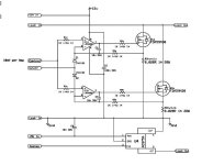
I tooks CamLights suggestions and modified the schematic accordingly. here it is:

Modular load_1_1.jpg


i also got a couple of the FDA59N30 MOSFETs and an ACS754-100 current sensor. now i just got to clean up a couple of milling jobs so i can start work on the Heatsink assembly and output module.

rick
 
rkosiorek said:
well Doc may be out of this because he now has a tricked out CBAII as well as a CC400. But I still need an active load for myself. so I am pressing on. I hope that you guys are still going to supply advice.

I tooks CamLights suggestions and modified the schematic accordingly. here it is:

View attachment 1


i also got a couple of the FDA59N30 MOSFETs and an ACS754-100 current sensor. now i just got to clean up a couple of milling jobs so i can start work on the Heatsink assembly and output module.

rick

Rick,

I'll still continu o this topic. that's great to get a CC--400 by that way! and that make me feel very happy and appreciate how great is this community :wink:

The desing of an electronic load is still interesting for me. I'll follow this topic carefully.

Doc
 
rkosiorek said:
well Doc may be out of this because he now has a tricked out CBAII as well as a CC400. But I still need an active load for myself. so I am pressing on. I hope that you guys are still going to supply advice.

rick
I'm happy to still help out any way I can. The schematic looks good!

I was wondering if it might be worth it to take the tops of each of the current-sense resistors and run them to an op-amp configured as a summing amplifier. The output of the amplifier would then be available as an indicator of the total current flowing to the load. If the op-amps are in a dual package, the second amp could be set up with some gain to bring the voltage level up. The ACS754 could still be used but since the resistors are always there generating a voltage based on the amount of current... :mrgreen:
 
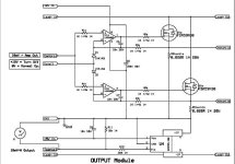
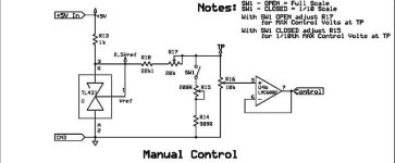
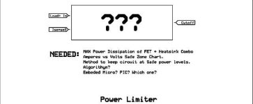
well after a bit of rest i have gotten back to this design. i have finished most of the schematic. but i am sort of stumped by the power limiter. first an update for the current schematics.

Output.jpg
Direct Ammeter.jpg
Manual Control.jpg
Power Supply.jpg
Limiter.jpg

I have a couple of fairly large heatsinks. with a fan each was used to dissipate 250W from some older Xeon server CPUs. (pulled from obsolete US Navy servers used aboard an undisclosed warship) i plan to mount one FDA59N30 FET and Fan on each of these heatsinks. theoretically these should be able to dissipate 500W as a pair being limited by the heatsink.

so the questions now are is this reasonable for these fets?

the other question is how to limit the power to a safe level for these devices. how do i develope a curve for the safe operating area for the module and what would be the best way to control this limit as the input voltage changes. Anyone have any suggestions?

rick
 
Back
Top