≤2000w 96V charger ~$5

DrkAngel said:
Switch is 60A.
Picture-schematic illustrates 2 variations of same cells.
So that would be 10A switching (not used) and 60A continuous, what voltage is that determined at 50Vdc? that's not a bad current throughput, as I'm assuming that the switch will be constantly connected on the ebike, 48V@60A.
Got to be careful when paralleling switches in shared current schemes as you can't be certain of equal power sharing.

Capacitor reactance XC = 1/(2πfC) and because the capacitor stores and discharges it also makes the voltage out of phase with the current, only a problem if you want to pull close to maximum charge power from a circuit without tripping the house circuit breaker or blow a fuse in the box.
If the phase shift cause a power factor of 0.7 the the circuit breaker must be around 1/(0.7 x charging power) = 1.43, so 2kw of bad boy is pulling close to 1.4 times the current of a p.f. corrected charger.
Just good to bear in mind if you love fast charging on big battery schemes and mum is doing the washing etc. :wink:

For a few more components, as cheap and smaller than a bulky series cap, http://m.ebay.com.au/itm?itemId=271206087419
http://m.ebay.com.au/itm/100-pcs-DB3-DB-3-Diac-Trigger-Diodes-DO-35-ST-/290562122407
http://m.ebay.com/itm/500K-ohm-3296-Multiturn-Trimmer-Potentiometer-10PCS-/400244721706

a simple SCR/TRIAC controlled charger is like simple pwm control, the circuit shown previously is self commutating arrangement and trigger level is adjustable using the potentiometer, the triac triggers and resets through zero, there's also less power factor issues and the gate control circuit has the big added advantage of being able to be controlled by BMS or cellog outputs and other control schemes.
 
WARNING! in case you didn't know Electricity is dangerous! ... to placate the fear mongers ...

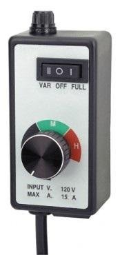
Regulated charge current controller.
Manual - adjustable Voltage + Amperage control!
To be used in conjunction with Volt-Amp meter and, mustn't forget, bridge rectifier.

≤ 15A for < $20 w/shipping


Begin tests at lowest setting and 5A fuse?

All these builds are designed to be continuously monitored!!!

Yeah ... I know, I know ... way more than $5.

WARNING! in case you didn't know Electricity is dangerous! ... to placate the fear mongers ...
 
i do have 1 of those!
i use it to slow down my die grinder.
so, free for me.
i don't know why these aren't popular on es? am i missing something? is it different design, as it is an AC motor speed control? (than the SCR dimmer)
 
Matt Gruber said:
i do have 1 of those!
i use it to slow down my die grinder.
so, free for me.
i don't know why these aren't popular on es? am i missing something? is it different design, as it is an AC motor speed control? (than the SCR dimmer)
Could be that you will need to have a pack, at near full voltage when rectified to get the maximum benifit.
I don't have a problem with that, electrical industry, but many would.
E.g you would have say an 104V 2P changed to a 208V 1P for charging off a 230V supply.
 
DrkAngel said:
Regulated charge current controller.
Manual - adjustable Voltage + Amperage control!
To be used in conjunction with Volt-Amp meter and, mustn't forget, bridge rectifier.

≤ 15A for < $20 w/shipping


Begin tests at lowest setting and 5A fuse?

All these builds are designed to be continuously monitored!!!

Yeah ... I know, I know ... way more than $5.

Hi DrkAngel

Do you have a link for where to buy this small control box ?

Or/and a brand name and part number ?

I can't find it :cry:

Thank's
 
http://www.harborfreight.com/router-speed-control-43060.html
 
WARNING! in case you didn't know Electricity is dangerous! ... to placate the fear mongers ...

IRON DOG said:
DrkAngel said:
Regulated charge current controller.
Manual - adjustable Voltage + Amperage control!
To be used in conjunction with Volt-Amp meter and, mustn't forget, bridge rectifier.

≤ 15A for < $20 w/shipping


Begin tests at lowest setting and 5A fuse?

All these builds are designed to be continuously monitored!!!

Yeah ... I know, I know ... way more than $5.

Hi DrkAngel

Do you have a link for where to buy this small control box ?

Or/and a brand name and part number ?

I can't find it :cry:

Thank's
Click on picture = Amazon
or
ebay etc., search for router speed control

WARNING! in case you didn't know Electricity is dangerous! ... to placate the fear mongers ...
 
as soon as i get the $3.60 SCR dimmer, i'll hook it to my grinder and see if it works any different.
 
I built the circuit I found and posted, it might need additional components to let it go through zero crossing somehow, as I think it was being held on by the charging battery and I lost a few triacs in the process, no big though, cheap as.
Though must find a way to get them to turn off
Not sure with the SCR similar operation, but unidirectional
 
There are zero crossing detector optoisolated triac drivers - MOC3021 IIRC.
 
heathyoung said:
There are zero crossing detector optoisolated triac drivers - MOC3021 IIRC.
Thanks heath, so these diacs will allow the triac to turn off even though the triac would be switching a bridge rectifier to say a 200V battery?
 
WARNING! in case you didn't know Electricity is dangerous! ... to placate the fear mongers ...

Received - 2000W SCR Voltage Regulator Dimmer Speed Temperature Controller AC 110-220V - $3.60

With 120V AC, I was able to adjust from 20V to 116V AC.
Voltage-amperage seemed accurate.
Adjusted at 75V through bridge rectifier, 3 30w leds (in series adjusted to 5w usage)

I tested it to death!
Literally.
Got some jumper wires crossed and a big flash and smoke, should have mounted properly rather than layed loosely on floor.
Rebuilt the traces but FET seems shorted ... full voltage with no adjustment.
Before I killed it I did get some measures:
300k pot
~20V @ 156K 1/3 travel, faults to 2.2V if turned further - 220V range adjustment?
116V @ ~0 ohms resistance
Thinking of replacing 300k with 100k pot(and 50k resister?) to tune desired operating range
Yes, ordered a couple more

Voltage-current seems regulatable in conjunction with a minor secondary drain ... small light or LED?
Bleed through, below regulation, seems to be a few meager watts.

WARNING! in case you didn't know Electricity is dangerous! ... to placate the fear mongers ...
 
DrkAngel said:
Yes, ordered a couple more
.
Make sure the bridge is after the dimmer and it could work, mine has been before it and got advice of Fechter to change the set up.
 
WARNING! in case you didn't know Electricity is dangerous! ... to placate the fear mongers ...

2000w SCR
Dial pot, 500k, seems parallel to "on board" multi turn, low voltage adjustment(?), pot.
I did not finish testing before it got cooked.

I ordered multiple "110-220V" samples for testing.
Also ordered cheaper "220V", which appears identical, will test.
Ordered from "China" which seems to ship faster than "Hong Kong". IMO

It seems important to have circuit complete before applying AC current.
Otherwise, there is an initial full voltage surge when connected.
A small (few watts) continuous draw seems to negate this initial "spike".

WARNING! in case you didn't know Electricity is dangerous! ... to placate the fear mongers ...
 
DrkAngel said:
2000w SCR
Dial pot, 500k, seems parallel to "on board" multi turn.
Yeh I think having multi turn adjustment will be needed to adjust the charging rate, a single turn pot might be too coarse an adjustment.

Hopefully your onto a winner Angel, you got half wave rectification with the SCR too, could work on it's own, hopefully battery will smooth out an otherwise very choppy output, like the idea of a Triac better though because I can, hopefully, just put the bridge in line and have full wave rectified, filling in and half as choppy, will know today.
 
These SCR controllers are designed to work into an inductive or resistive load. Working into a battery presents a very different situation, essentially it is a very low impedance load with back EMF.

Normally when the SCR fires the resistance or inductance of the load moderates the current (and note that their normal loads can handle the FULL line voltage in the first place). In the case of feeding a bridge into a battery the current peaks aren't very well moderated. When the SCR fires at a voltage below that of the battery there will be no current flow. When the firing voltage exceeds the battery voltage a very large current spike will result. These spikes will be very hard on the bridge and the SCR and may well exceed peak ratings and cause failures before they integrate to useful charge currents.

Add fuses and a quick disconnect for safety and experiment carefully so that a short cannot occur in temporary wiring and that a failure or fire during the test is not a disaster. Use components that are rated higher than expected to handle the high peak currents. Prepare ahead of time for potential problems.

Take care,
 
Alan B said:
These SCR controllers are designed to work into an inductive or resistive load. Working into a battery presents a very different situation, essentially it is a very low impedance load with back EMF.
,
Thanks for that, that's probably why they show the inductor in the patent diagram http://endless-sphere.com/forums/download/file.php?id=147590

Back emf is confusing, because it's not inductance related, but yeh there could well be current surge, good advice on that, with the safety aspects, anyone not using a suitable close rated breaker, of say 10A on a 10A draw circuit is asking for trouble and using personal protective equipment and making sure, if using any capacitors are discharged would be a must, I've been bitten by 240V a few times and lucky, I've been bitten by the rectified 240V and burnt a hole in the end of my finger, there's definitely a difference and anyone messing with this stuff should have at foundational grounding in electrical principles and electrical safety and know how to test for a live/dead circuit properly, with test equipment, for sure, this stuff can kill.
 
Alan B said:
These SCR controllers are designed to work into an inductive or resistive load. Working into a battery presents a very different situation, essentially it is a very low impedance load with back EMF.

Normally when the SCR fires the resistance or inductance of the load moderates the current (and note that their normal loads can handle the FULL line voltage in the first place). In the case of feeding a bridge into a battery the current peaks aren't very well moderated. When the SCR fires at a voltage below that of the battery there will be no current flow. When the firing voltage exceeds the battery voltage a very large current spike will result. These spikes will be very hard on the bridge and the SCR and may well exceed peak ratings and cause failures before they integrate to useful charge currents.

Add fuses and a quick disconnect for safety and experiment carefully so that a short cannot occur in temporary wiring and that a failure or fire during the test is not a disaster. Use components that are rated higher than expected to handle the high peak currents. Prepare ahead of time for potential problems.

Take care,

+1.
Size an appropriate inductor to add in series and you may have something.

Also, note that voltage control can only alter RMS voltage. All that matters when driving a filament or load with adequate inductance. However, if you charge a capacitor (or cell) it will still creep to ~150-170vdc, despite a good multi-meter telling you its true RMS voltage is 20vdc (or whatever it's set for).

Also, I agree with healthyyoung that a good fuse going in and out of this device is a great idea. It seems likely to blow in this useage, and in blowing can solidly short the battery and/or line voltage together (failing harmlessly is also possible fortunately!).
 
The problem with fuses Luke is they are open to abuse.
Once this circuitry is nailed by someone yeh the right fuse is all good.
But constantly replacing fuses, experimenting, leads to some people finding they have no fuses left, so the wrong one or a nail?
If your experimenting, have a breaker in line, lot safer and won't switch on to a outside of parameters problem like a short circuit.
 
With a small toroid in line, I think it was part dealing with the in-rush and as figured, found the triggering point much too coarse with a 500k pot, it starting to pull some serious amps did'nt measure it, but could hear the breaker, getting ready to trip, a few seconds in, could have been 40A+ @ 118V, on partially depleted lipo 30S/8Ah, around 125V full charge, plus only had a single turn pot, as soon as the triac triggering, it must have already been well conducting over too much of the wave.
Might have to get bigger components :mrgreen: .
Like you mention angel it would be good to set the fixed value resistor, for a fixed pack use, under your low voltage depleted pack value and have a fine multi-turn pot, or redesign the triggering circuit slightly, would need it for an alarm trigger anyhow.
 
WARNING! in case you didn't know Electricity is dangerous! ... to placate the fear mongers ...

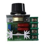
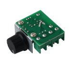
2000w SCR is a Silicone Controlled Rectifier
Extremely simple and inexpensive! < $5

2k SCR.jpg2k SCRb.jpg
They provide effective voltage regulation.
In series with a bridge rectifier they also can supply adjustable "rough" DC current.

My first mod will be to trim for 110V USA voltage.

Present adjustment is a 500k dial pot in parallel with a 1M(?) multi-turn pot, (220V model).
Replacing 500k with 200k should make much more 110V friendly.

LED testbed
Then further "adjust" for lower voltage use.
Such as 27- 35V high output LED modules.
(I charge at ~29V and ~36V - 7s and 9s packs)
To test, I will mount a 30w 34V DC LED chip on a good heatsink
Adjust voltage to rated 34V
Confirm a match to the rated ~900mAh 30w DC input.
Compare to my AC metered supply, to confirm Watt and determine rectifier efficiency %.

And run continuously, looking for:
LED, mAh, watt, lux output deterioration.
To determine LED durability when subjected to rough DC.


Yes, and of course, I will test, document and report on battery charging feasibility.
Will run initial battery charge circuit through a 100w light bulb, as safety-fuse-current regulation.
Next stage will be a minimal voltage differential with a low amp fuse as safety.
I will begin with SCR set to minimal voltage , then adjust up, monitoring volt-amp-watt level.
Bridge rectifier will prevent circuit voltage backwash.

At minimum, this device should provide adjustable voltage and current for charging, though you might need to manually restrict current by reducing initial charge voltage.

There is still the bleed through of rectified voltage peaks to consider.
A minimal drain device in parallel with battery might regulate this effectively?

WARNING! in case you didn't know Electricity is dangerous! ... to placate the fear mongers ...
 
I know you're into keeping the parts cost in the single digit range, but playing with the Triac's without an inductor driving a load that is so stiff with capacitance and natively has low inductance (like a battery) is going to cost you more money than buying something like this to put in series with your load:

http://www.ebay.com/itm/Homemade-Choke-Inductor-Coil-20A-DC-367uH-for-filtering-DC-power-supply-/221542726797?pt=US_Cardio_Treadmills&hash=item3394f9bc8d


Or, if you must make it cheaper, there are many inductor alternatives to play around with.
http://www.ebay.com/itm/20pcs-Toroid-Core-Inductor-Wire-Wind-Wound-for-DIY-100uH-6A-/390738766364?pt=US_Radio_Comm_Coaxial_Cables_Connectors&hash=item5af9d86a1c

My hunch is that you're going to want iron as your core material over ferrite, as I suspect the switching speed of the Triac is too low to take advantage of ferrite. Perhaps the ultimate would be a ferrite core type to handle the fast current spikes:

http://magnetic-components.mpsind.com/viewitems/gnetic-components-inductors-high-current-inductors/tors-h1000-series-flat-wire-high-current-inductors?

And something iron core like the first link to handle the bulk of the current smoothing.
 
I'm hoping to minimise the inrush on cycles by sneaking up on the trigger point.
Correct me if I'm wrong, I only got to electronics tech, I think this has a minimum differential value, somewhere on the device G to MT2 or something.
With a fine control pot, sneak up to the triggering point and watch the current value on triggering, if excessive increase series inductance.
With transients a TVS/ MOV could catch them, think we're officially over the $5 mark now :mrgreen:

Angel, your in line choke on that SCR is teeny too, like non existent, that's why this kind of gear is normally a no no and still a good bad boy, it's going to be electrically noisy as and I bet oldies on the long waves will love it too :pancake:
 
WARNING! in case you didn't know Electricity is dangerous! ... to placate the fear mongers ...

Being a comparative neophyte to electronics, I am having problems understanding explanations of inductor functions.
(I have a working understanding of pots, caps, diodes, resistors, multiple transistor types + basic theory on a bit more)

If I understand correctly:
An inductor, in series, on the draw of rough DC (rectified AC or PWM DC) will smooth-center-stabilize the DC.

Where explanations seem unclear (to me):
An inductor will limit ("choke") current if placed "in line" on the DC, but on AC somehow differently?

Bonus questions:
If on the DC side, would 2 - "6A" inductors in parallel regulate at 12A or just smoother 6A DC?
If on the AC side, would 2 - "6A" inductors in parallel regulate at 12A?

WARNING! in case you didn't know Electricity is dangerous! ... to placate the fear mongers ...
 
Going back a ways now.
If i remember rightly Capacitor dv/dt,
Inductor di/dt.
The capacitance will try to oppose a rise in voltage.
The inductance will try to oppose a rise in current, by applying a back EMF.

The 2 parallel inductors will effectively double your current, but half the inductance.
 
Back
Top