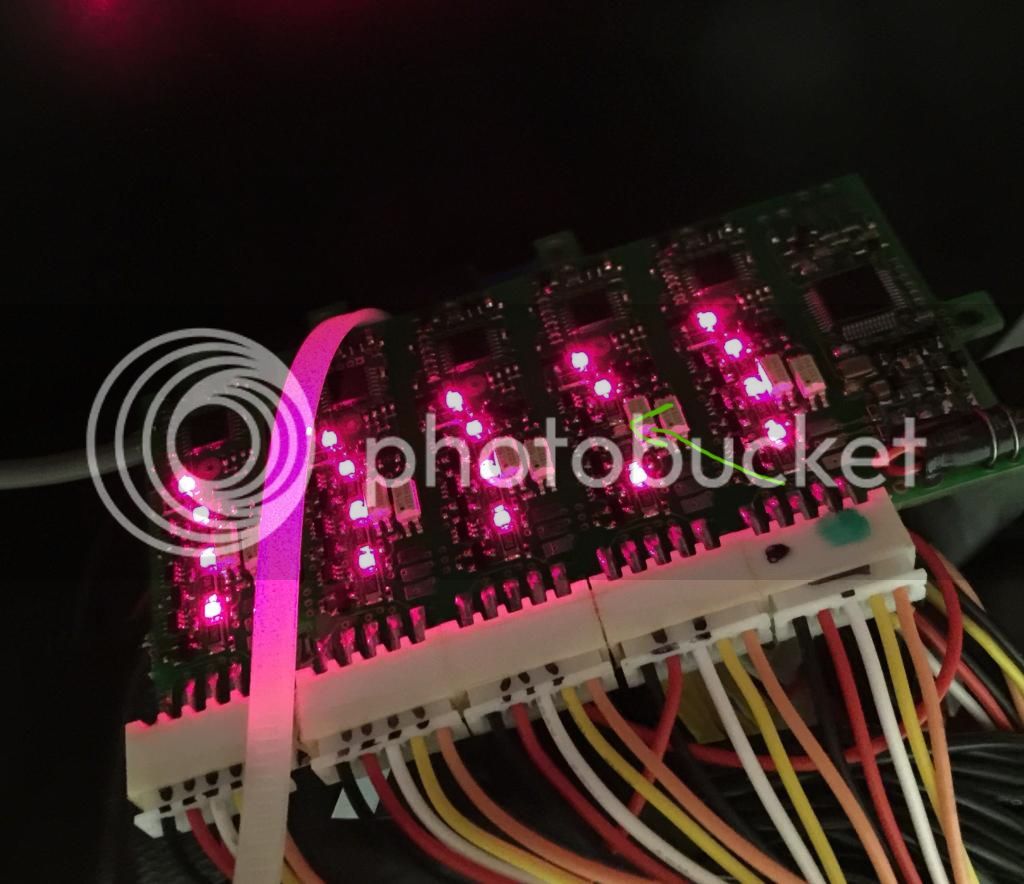
Adaptto Mini-E/Max-E Owner's Thread

GreenRoad said:
To the motor settings... the adaptto settings of the autosetup are quit strange.
I get out differnt settings depending if the motor has an temperature of 20°c or 50°C - okay this could be normal and its physics.
But also interesting is, that i get out differnt settings of the fine Hall Offset, depending on the switched Phase wire.
Normaly i have 1 - 2° difference, but i also get out 13°if i use another Wire connection.... thats strange - because i do not know whats the right.

Tomorrow i should get an new Motor with another winding configuration - iam verry interested what settings i getting out.

The problem now is, that with the actual autosettings i only could drive about 1minute up to 50Amps, after that i also have a power of max 5A and i could stop the wheel with my hand - (Adaptto overheating protection?) - that means that something should be wrong with the settings but i do not know what that could be.
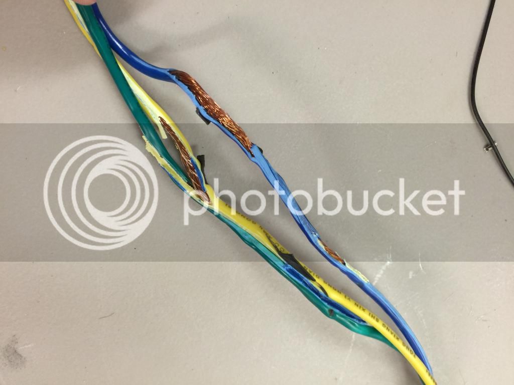
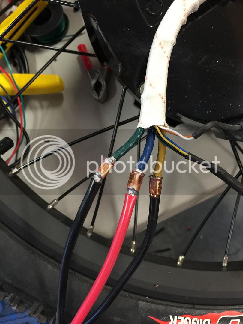
I used the same motor with more coil windings without any problem and now we reduce the winding - i get the problems.

That's interesting...

So you noticed that the autosetup give you different settings according to the winding temp and also phase connections?

My tought woudl be that each of your 3 phase dont have the exact same inductance and resistance. I already have two of my motor that vary of about 10-15% in inductance forn onw phase to phase commections to another... Later on one of my motor i have discovered that i had one strand that was broken on my 5302 witch have usually 10 parallel strands. So one of the phase had only 9 strands. I guess the Adaptto use the measureent on one of the phase to phase combinaison only and not the average of the 3... but i remember that in teh manual it was said that it was actually doing an average of the 3 hall offset to calculate teh offset.. so this might not be the same for the phase wires resisatnce auto test...

Doc
 
Hello Doc
yes - it true i also read about the hall sensor Offset - the measure every sensor and make an middle value.
Thats strange that i get here differnenc values - because i placed the hallsensor for myself at 120° and the value up to 2° differenc schould be okay.
Also if the temperature changes, because i glue the sensors direct to the windings...

I will check the winding of the motor, if there are an mistake,.... im am waiting for an other motor, with some windings more than i have now.
i will tell you what i finding out.
 
according to the manual....

2.2.16 All-wheel drive mode
Optional 2WD mode used to connect a second slave controller to operate a second motor. From the menu, you can enable / disable the second motor, and set the maximum vehicle speed at which the second motor will run. For example when using a planetary geared motor with an over running clutch as a slave, you can set it to turn off when it reaches a preset speed, since it only acts as an helper at startup and low speeds or in those situations like climbing where the main direct-drive motor may not be sufficiently effective. The slave controller must have an additional connector. The additional connector is not included as standard and must be ordered separately.

3.3.7 Traction settings
2WD enable – enables/ disables all-wheel drive mode. A second controller can be connected to the peripheral bus of the main controller. The slave controller is controlled by the main controller, if this option is enabled.
Slave SL - When this speed is reached, the second additional controller is disabled. It is recommended to use this setting if in 2WD mode, the second motor has a planetary gear and overrunning clutch and helps only at low speeds and at high speeds spins uselessly.

does anyone know if the 2nd controller has to be an Adaptto, or if it can be a different make controller ?

(I'm guessing it has to be another adaptto, but it's worth asking before I buy a mini for the front wheel)
 
knighty said:
according to the manual....

2.2.16 All-wheel drive mode
Optional 2WD mode used to connect a second slave controller to operate a second motor. From the menu, you can enable / disable the second motor, and set the maximum vehicle speed at which the second motor will run. For example when using a planetary geared motor with an over running clutch as a slave, you can set it to turn off when it reaches a preset speed, since it only acts as an helper at startup and low speeds or in those situations like climbing where the main direct-drive motor may not be sufficiently effective. The slave controller must have an additional connector. The additional connector is not included as standard and must be ordered separately.

3.3.7 Traction settings
2WD enable – enables/ disables all-wheel drive mode. A second controller can be connected to the peripheral bus of the main controller. The slave controller is controlled by the main controller, if this option is enabled.
Slave SL - When this speed is reached, the second additional controller is disabled. It is recommended to use this setting if in 2WD mode, the second motor has a planetary gear and overrunning clutch and helps only at low speeds and at high speeds spins uselessly.

does anyone know if the 2nd controller has to be an Adaptto, or if it can be a different make controller ?

(I'm guessing it has to be another adaptto, but it's worth asking before I buy a mini for the front wheel)

As i know, it must be an adaptto - the comunicate between the bus system.
Surly you can use also another controller, but the main thing to use 2 motors is the traction control ---- thats the main problem of the use of two motors at one bike - they must run synchron - otherwise the bike is not to handle.
If you use motors with freewheel - its easier to drive, but i never tried an direct motor........
 
Doctorbass said:
That's interesting...

So you noticed that the autosetup give you different settings according to the winding temp and also phase connections?

My tought woudl be that each of your 3 phase dont have the exact same inductance and resistance. I already have two of my motor that vary of about 10-15% in inductance forn onw phase to phase commections to another... Later on one of my motor i have discovered that i had one strand that was broken on my 5302 witch have usually 10 parallel strands. So one of the phase had only 9 strands. I guess the Adaptto use the measureent on one of the phase to phase combinaison only and not the average of the 3... but i remember that in teh manual it was said that it was actually doing an average of the 3 hall offset to calculate teh offset.. so this might not be the same for the phase wires resisatnce auto test...

Doc
10% - 15% should be okay - you could try to rotate the magnetic ring - so you also get out different values for inductance.
The resitance should be nearly the same.
I never ever do a lot of measuremt of motor coils...
The only test in past was the high voltage test, to find out winding shorts - the crystalyte motors sometimes have them...
 
Hey guys, I'm back for more advice...

I got the Max-E working with the BMS on Thursday. So I was having lots of fun over the weekend.

Sunday I had a little too much fun, and was blasting up a hill by my house.

I noticed I hit about 10kW and the bike stuttered and stopped. Controller and motor temps were low, but my donor phase extensions had melted. These were undersized leads that were cut from a Crystalite 3540.

As you can see the coating melted shorting out the phase wires.
5787EF69-F6BA-441C-82A2-46275F197A00.jpg


Coincidentally, my 8 gage welding cable showed up that same day. So I replaced the phase leads.
FD6F4E03-33AF-4114-B56C-E59F5964D9E9.jpg


Unfortunately, now I can't get the controller to do anything, as it complains about "Halls Error 2"

Weird thing is that I get this error even if I switch to Sensorless mode.

Any thoughts?
 
zlagger said:
Hey guys, I'm back for more advice...

I got the Max-E working with the BMS on Thursday. So I was having lots of fun over the weekend.

Sunday I had a little too much fun, and was blasting up a hill by my house.

I noticed I hit about 10kW and the bike stuttered and stopped. Controller and motor temps were low, but my donor phase extensions had melted. These were undersized leads that were cut from a Crystalite 3540.

As you can see the coating melted shorting out the phase wires.
5787EF69-F6BA-441C-82A2-46275F197A00.jpg


Coincidentally, my 8 gage welding cable showed up that same day. So I replaced the phase leads.
FD6F4E03-33AF-4114-B56C-E59F5964D9E9.jpg


Unfortunately, now I can't get the controller to do anything, as it complains about "Halls Error 2"

Weird thing is that I get this error even if I switch to Sensorless mode.

Any thoughts?
About the !HALLS !, there is a resistor that you have to replace in the controller pcb that is on the opposite end of the wires input. I also had this problem and replaced the protectin SMT resistor R113 and everything worked again!

Take a look here: http://electrotransport.ru/ussr/index.php?topic=23722.0 use google translate :wink:

Here is my thread about the Adaptto and NYX bike. I am describing the problem and solution at the end of the page: http://endless-sphere.com/forums/viewtopic.php?f=3&t=65764

Btw, Jeka is the engineer of the Adaptto.

Doc
 
go into the debug monitor and try to spin the wheel.
Check if the Hal stats are chainging - you also see an Text which should change from H6,H5 H4 H3 H2 H1
if you get this - the Hall sensors are okay

I also found out, that you get an hall failure, if one phase is not connected.

Check if the sensor are okay ore not - otherwise you have to open the motor to take a look inside...
 
Thanks Doc

I will look into that.

Doctorbass said:
zlagger said:
Hey guys, I'm back for more advice...

I got the Max-E working with the BMS on Thursday. So I was having lots of fun over the weekend.

Sunday I had a little too much fun, and was blasting up a hill by my house.

I noticed I hit about 10kW and the bike stuttered and stopped. Controller and motor temps were low, but my donor phase extensions had melted. These were undersized leads that were cut from a Crystalite 3540.

As you can see the coating melted shorting out the phase wires.
5787EF69-F6BA-441C-82A2-46275F197A00.jpg


Coincidentally, my 8 gage welding cable showed up that same day. So I replaced the phase leads.
FD6F4E03-33AF-4114-B56C-E59F5964D9E9.jpg


Unfortunately, now I can't get the controller to do anything, as it complains about "Halls Error 2"

Weird thing is that I get this error even if I switch to Sensorless mode.

Any thoughts?
About the !HALLS !, there is a resistor that you have to replace in the controller pcb that is on the opposite end of the wires input. I also had this problem and replaced the protectin SMT resistor R113 and everything worked again!

Take a look here: http://electrotransport.ru/ussr/index.php?topic=23722.0 use google translate :wink:

Here is my thread about the Adaptto and NYX bike. I am describing the problem and solution at the end of the page: http://endless-sphere.com/forums/viewtopic.php?f=3&t=65764

Btw, Jeka is the engineer of the Adaptto.

Doc
 
Thanks for the heads up, this checks ok..
Must be the resistor, or another issue in the motor.
GreenRoad said:
go into the debug monitor and try to spin the wheel.
Check if the Hal stats are chainging - you also see an Text which should change from H6,H5 H4 H3 H2 H1
if you get this - the Hall sensors are okay

I also found out, that you get an hall failure, if one phase is not connected.

Check if the sensor are okay ore not - otherwise you have to open the motor to take a look inside...
 
Hello
You could measure the wire resistance
perhaps (i think) at the axle also an wire is mold.

(At my situation i also get an Hall failure if a phase wire is not connected)

Open the motor and take a look inside - than you could see more.

i always change the wire of the crystalyte motor, if i use more power 8)
 
A have finished the work on the BMS and now I'm trying to find a solution for the charging coil. I want to DIY it as I have all the material except the "E" core for the 70A coil.

With some help I have found the big "E" shape transformer core to build the big 70A charge coil.

These are available in North America here:

From Digikey:
http://www.digikey.ca/product-search/en?lang=en&site=ca&KeyWords=B66371G0000X187+&x=0&y=0

From mouser:
http://ca.mouser.com/ProductDetail/EPCOS/B66371G0000X187/?qs=/sLciWRBLmDB7SRILGAnRw==

Doc
 
So, I found out the motor Halls and Phase leads are ok. There is definitely something wrong with the controller though.

I switched to my mini-E and everything is working again.

Well auto detect is no good with this motor.
 
zlagger said:
So, I found out the motor Halls and Phase leads are ok. There is definitely something wrong with the controller though.

I switched to my mini-E and everything is working again.

Well auto detect is no good with this motor.


The way you soldered the phase wire with the little copper can is the best way to do :wink:

Doc
 
Has anyone successfully run a Crystalite Crown motor with the Adaptto?

Seems like calibration is way off. The Mini-E was over heating in less than 1/2 a mile. Had to switch to Sensorless to get to work. Then it ran cool.

Upgrading to newest firmware presently, will try that next
DF6671E3-199C-4FF5-9939-64496D49562C.jpg
 
Wire resistance detection was WAY lower after I switched to the bigger wire and soldered copper cans.

Doctorbass said:
zlagger said:
So, I found out the motor Halls and Phase leads are ok. There is definitely something wrong with the controller though.

I switched to my mini-E and everything is working again.

Well auto detect is no good with this motor.


The way you soldered the phase wire with the little copper can is the best way to do :wink:

Doc
 
Newest firmware fixed the auto detect issue. The bike is running pretty good now. Wish it was the Max-E, but the mini will have to do for now.

Did my first coil charge tonight. Works great. Noticed that one LED on the BMS doesn't lite up, even though all cells were over the balance threshold. Not sure yet if it's just the LED or if that circuit is not balancing.
F652299B-EADA-4195-B663-9B0A865D6E98.jpg
 
Doctorbass said:
A have finished the work on the BMS and now I'm trying to find a solution for the charging coil. I want to DIY it as I have all the material except the "E" core for the 70A coil.

With some help I have found the big "E" shape transformer core to build the big 70A charge coil.

These are available in North America here:

From Digikey:
http://www.digikey.ca/product-search/en?lang=en&site=ca&KeyWords=B66371G0000X187+&x=0&y=0

From mouser:
http://ca.mouser.com/ProductDetail/EPCOS/B66371G0000X187/?qs=/sLciWRBLmDB7SRILGAnRw==

Doc

Hello Doc
iam verry interested if this work.
I tried to use this coil
http://www.mouser.at/ProductDetail/Coilcraft/SER2915H-153KL/?qs=%2fha2pyFaduiUuF4tEj8f6h5oS8GadgLX88Ny5DPbjGqZhjBdzeIYRziceSg3nlkg

But it did not work - the coil getting to warm - allready at 10Amps.
So thats why i stopped the charging coil project an use the original coil....
 
zlagger said:
Newest firmware fixed the auto detect issue. The bike is running pretty good now. Wish it was the Max-E, but the mini will have to do for now.

Did my first coil charge tonight. Works great. Noticed that one LED on the BMS doesn't lite up, even though all cells were over the balance threshold. Not sure yet if it's just the LED or if that circuit is not balancing.
F652299B-EADA-4195-B663-9B0A865D6E98.jpg

if you charge all cells well over the set ballance voltage and the led still doesnt shine then theres a good chance its a dud.
 
If the led does not shine - it could also that this led is bad - or wrong mounted.
It would be interested to test if this cell string are balanced or not - i do not know if this is visible at the adaptto display.

But it will check this, because this could be also a bad bms...
 
have you checked voltage across the LED?
 
Oleg from Adaptto said that 99% of the time if there is no LED, that cell is dead.

ridethelightning said:
zlagger said:
Newest firmware fixed the auto detect issue. The bike is running pretty good now. Wish it was the Max-E, but the mini will have to do for now.

Did my first coil charge tonight. Works great. Noticed that one LED on the BMS doesn't lite up, even though all cells were over the balance threshold. Not sure yet if it's just the LED or if that circuit is not balancing.
F652299B-EADA-4195-B663-9B0A865D6E98.jpg

if you charge all cells well over the set ballance voltage and the led still doesnt shine then theres a good chance its a dud.
 
I will test the LED tonight when I charge again. I checked the cell voltages on the Adaptto display after the bike balanced for 10 minutes (charger off) and they looked nicely balanced. Thing is, I don't know if that cell was pushed over the balance threshold all that much.

GreenRoad said:
If the led does not shine - it could also that this led is bad - or wrong mounted.
It would be interested to test if this cell string are balanced or not - i do not know if this is visible at the adaptto display.

But it will check this, because this could be also a bad bms...


madin88 said:
have you checked voltage across the LED?

Madin88, this is such an obvious thing to do, but I did not check. Thanks for the suggestion.
 
I am really not sure if I need to be changing the R113 as Voltage supply for the Halls is good. 4.64V on pin 6,5. I see on Crea2k3's photo below that he had a much lower voltage. If the R113 is blown, wouldn't voltage be lower?
volts.jpg
 
Back
Top