Any hack to get this solar charger panel working

LoneeagleR

10 µW
Joined
Sep 11, 2023
Messages
5
Location
Ohio
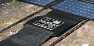
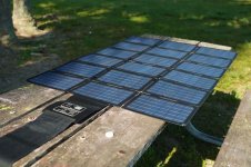
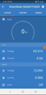
Hi, a newbie at ebike's and solar. I would like to use a solar panel that's (150watt DC ousput 58.8V 2.55A Max that's made for recharging my ebike. I have a Victron SmartSolar Charge Controller MPPT 100v/15a that I hooked it up to. When connected the voltage readings from it jump around from 63 to 1, to 0. it' does the same when I try getting a multimeter reading from it. It's not stable enough for the mppt to lock on to charge a battery. It may be a bad ebike solar charger or I'm thinking maybe the ebike solar charger's controller is looking for a battery to lock on to not the mppt controller. Is there any hack to get this solar charger panel to stop jumping around and send steady voltage on through to the mppt controller so it can charge 12V Liefpo4 batteries I have.
 

Attachments

  • Recorder_11092023_155128.gif
    Recorder_11092023_155128.gif
    101.6 KB · Views: 3
Last edited:
Does the panel have electronics in it already? If so, you'd probably have to bypass those*** and connect the panel directly to your Victron, as.

(the 58.8v sounds like it has a built in "52v" charger in it already, for a typical 14s ebike battery).

You'll probably have to disconnect the built in stuff from the panel wiring, but it might be possible to just parallel the Victron panel connnections with the built in electronics' panel connections. (I suspect the one will interfere with the other)
That's what I was thinking the two mppt's won't work together is why the panel was looking like it was going on and off in voltage looking for a battery I thought. Do a bypass? I don't know electronics that well but if someone could tell me how to bypass or adapt it to work with the Victron controller . I really would like to be able to use this 52v solar charger for my bike and battery for charging when camping. I have a Bluetti pv120 it has no problem going through the Victron controller to charge 12v batteries but it's too bulky to carry on a ebike and slow charging.
 
That's what I was thinking the two mppt's won't work together is why the panel was looking like it was going on and off in voltage looking for a battery I thought. Do a bypass? I don't know electronics that well but if someone could tell me how to bypass or adapt it to work with the Victron controller .

Bypass means physically disconnect the wires from the panel to the built in MPPT / charger, so that the only thing you have is the solar panel itself.

Then you connect the Victron in place of the built in stuff.


I really would like to be able to use this 52v solar charger for my bike and battery for charging when camping.

If you want to use the panel itself for two different things, you'll probably have to install connectors on the panel wires so you can plug in either the original built-in MPPT/charger, or the Victron. Whenever you're going to change the connection, I recommend putting a blanket over the panel so there's no voltage present on it's output. (or doing it at night).
 
Bypass means physically disconnect the wires from the panel to the built in MPPT / charger, so that the only thing you have is the solar panel itself.

Then you connect the Victron in place of the built in stuff.


If you want to use the panel itself for two different things, you'll probably have to install connectors on the panel wires so you can plug in either the original built-in MPPT/charger, or the Victron. Whenever you're going to change the connection, I recommend putting a blanket over the panel so there's no voltage present on it's output. (or doing it at night).
Thanks
 
I suggest the complete disconnection of one before connecting the other so you don't have to worry about either one potentially damaging the other.

If you're not risk-averse, you can first try the victron directly connected to the panel wires (the same ones that connect the panel to the built in stuff), and see if it works that way. You probably can't connect both of them to a load at the same time, though.
 
This thing looks like it was built so no one could get into it. It's sealed all around, and wires from the the panel are flat and integrated into the black panel plastic piece coming from the solar panels. The only way in it is to slice the top off that I can see. And then the flat wires used to the controller might be another problem. The usb-c PD port works. It puts out 12v but not enough to start the Victron controller. I wonder can a 12v to 24v booster be put between the usb-c PD port and the Victron controller to boost it enough to charge? It puts out a steady 12v.
 

Attachments

  • electric-bike-battery-solar-charger-2.jpg
    electric-bike-battery-solar-charger-2.jpg
    166.6 KB · Views: 6
  • electric-bike-battery-solar-charger.jpg
    electric-bike-battery-solar-charger.jpg
    278 KB · Views: 6
AFAIK the victron, if an MPPT, would be designed to source power from the panel itself, with it's electronics designed not to deal with a simple voltage source, but the variable resistance, voltage, and current of the panel itself. You'd have to check its' manual if it has a simple voltage-input mode and use that if you're not running it from a panel directly.

Otherwise I think you are probably best off either getting a separate panel for the victron to run from, or skip using the victron entirely and use a normal DC-DC that will run off your ebike battery and give you the voltage and current-limited output that you are after. Then leave your bike battery connected to the charger output of the panel so it can stay topped off while you're doing this.

This DC-DC will have to be a charger in it's own right, that has an output compatible with your LiFePo4 pack's charge input (the right full-charge voltage, and CC/CV output type that limits current the same way a charger or LED PSU does, rather than the way most DC/DC's do which is to shutdown once past their current limit...but it *has* to be current limited to a safe limit for the input of your LFP pack, *and* it can't use more power (Watts) than the output of your battery can supply.. W is V x A, so whatever the total output at max charging current the LFP pack would ever draw is times the volts it charges at, is the watts it supplies...the watts it takes out of your other pack will be higher than this, you can use 1.25x that for a good guesstimate (it could be less, or more, but that's a usually-safe number). Then divide that watt number by the ebike battery volts, and that gives you the ebiek battery output amps it has to supply to do the job.


It's not as efficient as running hte victron right off the panel, but it means you won't be potentially destroying things by opening them up and connecting / disconnecting things, or potentially overloading outputs of the built in electronics by drawing more current than they can supply or putting a kind of load on htem they can't handle (weren't designed for), etc.

It's no less efficient than trying to use a DC-DC to get the 12v output up to 24v and then running the victron off of that, and it's safer, since the battery can handle continuous or peak current of probably more than the panel's electronics can.
 
Last edited:
AFAIK the victron, if an MPPT, would be designed to source power from the panel itself, with it's electronics designed not to deal with a simple voltage source, but the variable resistance, voltage, and current of the panel itself. You'd have to check its' manual if it has a simple voltage-input mode and use that if you're not running it from a panel directly.

Otherwise I think you are probably best off either getting a separate panel for the victron to run from, or skip using the victron entirely and use a normal DC-DC that will run off your ebike battery and give you the voltage and current-limited output that you are after. Then leave your bike battery connected to the charger output of the panel so it can stay topped off while you're doing this.

This DC-DC will have to be a charger in it's own right, that has an output compatible with your LiFePo4 pack's charge input (the right full-charge voltage, and CC/CV output type that limits current the same way a charger or LED PSU does, rather than the way most DC/DC's do which is to shutdown once past their current limit...but it *has* to be current limited to a safe limit for the input of your LFP pack, *and* it can't use more power (Watts) than the output of your battery can supply.. W is V x A, so whatever the total output at max charging current the LFP pack would ever draw is times the volts it charges at, is the watts it supplies...the watts it takes out of your other pack will be higher than this, you can use 1.25x that for a good guesstimate (it could be less, or more, but that's a usually-safe number). Then divide that watt number by the ebike battery volts, and that gives you the ebiek battery output amps it has to supply to do the job.


It's not as efficient as running hte victron right off the panel, but it means you won't be potentially destroying things by opening them up and connecting / disconnecting things, or potentially overloading outputs of the built in electronics by drawing more current than they can supply or putting a kind of load on htem they can't handle (weren't designed for), etc.

It's no less efficient than trying to use a DC-DC to get the 12v output up to 24v and then running the victron off of that, and it's safer, since the battery can handle continuous or peak current of probably more than the panel's electronics can.
Thanks that more than I can do right now. I'm going to check on this item: USB Type C 3.1 PD to 5.5mm Barrel Jack Cable - 20V 5A Output
using the USB Type C PD output on the solar panel. This cable says It says it can trigger the output to go to 20v possibly instead of the 12v I get from it. Then the higher voltage may trigger the Victron solar charger into turning on and then charge a battery.
AFAIK the victron, if an MPPT, would be designed to source power from the panel itself, with it's electronics designed not to deal with a simple voltage source, but the variable resistance, voltage, and current of the panel itself. You'd have to check its' manual if it has a simple voltage-input mode and use that if you're not running it from a panel directly.

Otherwise I think you are probably best off either getting a separate panel for the victron to run from, or skip using the victron entirely and use a normal DC-DC that will run off your ebike battery and give you the voltage and current-limited output that you are after. Then leave your bike battery connected to the charger output of the panel so it can stay topped off while you're doing this.

This DC-DC will have to be a charger in it's own right, that has an output compatible with your LiFePo4 pack's charge input (the right full-charge voltage, and CC/CV output type that limits current the same way a charger or LED PSU does, rather than the way most DC/DC's do which is to shutdown once past their current limit...but it *has* to be current limited to a safe limit for the input of your LFP pack, *and* it can't use more power (Watts) than the output of your battery can supply.. W is V x A, so whatever the total output at max charging current the LFP pack would ever draw is times the volts it charges at, is the watts it supplies...the watts it takes out of your other pack will be higher than this, you can use 1.25x that for a good guesstimate (it could be less, or more, but that's a usually-safe number). Then divide that watt number by the ebike battery volts, and that gives you the ebiek battery output amps it has to supply to do the job.


It's not as efficient as running hte victron right off the panel, but it means you won't be potentially destroying things by opening them up and connecting / disconnecting things, or potentially overloading outputs of the built in electronics by drawing more current than they can supply or putting a kind of load on htem they can't handle (weren't designed for), etc.

It's no less efficient than trying to use a DC-DC to get the 12v output up to 24v and then running the victron off of that, and it's safer, since the battery can handle continuous or peak current of probably more than the panel's electronics can.
Thanks. I have some options to try now Not sure how this diagram will work but I've seen something hooked up similar that worked charging a power station. I'll disconnect the solar panel after the 52v battery is charged then use it on the solar controller charger to charge the 12v battery. I'll have to wait 66 days for the 52v battery w/bms to get here from China, If it works I'll be happy.
Solar Block  Diagram Charging Battery.jpg
 
Back
Top