APL's DIY axial-flux motor

fechter said:
If you can get the desired number of turns with a single strand then that tends to be the easiest to build and the coils will have more mechanical strength.

Never tried it myself, but are you sure? It seems a bit counter intuitive, I would have thought that it would be much harder to bend a thick wire than just having to wind multiple thin ones. Did I miss someting somewhere?

Also, one other benefit of multiple strands is that it is usually said that it can get more dense than single ones, so you should be able to get a better copper cross section in the end, thus, more current passing through.
I'm not sure what are the actual disavantages of multi strand.
 
It’s true what fechter said, it’s for sure easier to wind with thin wire but the unavoidable hundreds of wire crossings and high wire insulation to copper ratio gives you lower fill percent in the slots.

Anything above a true 50% copper fill is good but i haven’t seen it in any thin wire windings.

Added bonus to the thicker wire is that the enamel can take a lot of abuse where the thin wires are quite sensitive to damages over lamination edges and stator carrier.

Off course motors like the c80100 with hair thin wires are still good enough motors, when they work.
 
The real PITA of using multiple strands is stripping and joining the ends. I guess if you have the magic insulation dissolver stuff it might not be too bad, but I've always had to individually try to strip the insulation off each strand. Winding is easier, as it is more flexible.
 
Most motors are radial, and multi strand is usually used for flexibility through the slots, and although multi strand 'can'
be wound nice and flat and all in a row, it would take a lot of effort with ten strand, and so not likely to happen.

Axial's have the same problem sometimes, but when the cores are removable, like this one, then single strand becomes
an option. I had trouble on the last motor with pinched fine wires, and shorts, like larsb said, and single strand fixed it.

On the other hand, when you get up into the 14 awg and above single strand, it gets a bit hard to work with too. I could
see using two strands instead of one, maybe. Might be easy to keep them lined up too.

I think your right about smaller wires having better fill though, as long as you can arrange them right. I'm sure I read it
somewhere,.. also better for eddy currents in high speed motors, I think.

I know I'm not getting the best fill factor with 14 awg, but the stuff is bullet proof, and thats worth a lot to me.
Lots about windings on Wiki; https://en.wikipedia.org/wiki/Coil_winding_technology

Stripping is always the problem with multi strand for sure, and the orange 200C enamel is even worse, it's supposed to be
a double coat, and much tougher. If you want to shorten, or change any connections, then you get to do it all over again.
With single strand, I can use the Dremel tool with a small sanding drum, and it goes pretty fast.

Depends on how accessible the connection is, if it's in the motor, then multi strand can be a real bear.

But then theres also the problem of soldering two 14 awg wire ends,.. it's not so easy to do very nice. I've been using a
piece of brass tubing, and crimping them inside first.
 
I finished machining the spacers for the 20T coils, wound up the cores with 20 turns, and gave it the spin test again.
Surprisingly unsurprising,.. it came out to exactly 2v at 550 rpm.

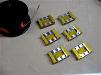
Spacers machined for 20T..jpg

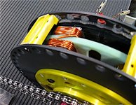
20T coil..jpg

So thats good news, and it also gives me a better idea of how long of a wire I'll need for each core, so I don't order too
much. Since I have 1.5 lbs of 14 awg already, I might as well go with that, and get this show on the road.
We'll see what this does, and if it don't work out, then so be it,.. I'll re-wind later.

I decided to give My Crystalyte motor a no load test, to see where thats at, and it came out to 426 rpm at 40.8v. So if
the 10.4 Kv figure is correct, then we are right in the ball park, at a predicted 410 rpm. (20T)

Only way to find out is to wind it and grind it,.. so I say go for it. :)
 
Looks really nice! You shouldn't have much problem with the windings moving around. Are you going to try winding all of them with the cores in place?

You also have the advantage of being able to change the gearing, so you can optimize for a wide range of turns counts.
 
Think I'm going to try and wind every other one in place, and then do the rest separate. I'll have to see how it goes.
I need lots of room to toss an 8 foot piece of wire around, and it can't twist, which makes it a little more difficult,..
like winding up a garden hose.

I had to uncoil it to get the cut length, but I'll have to coil it back up again for winding next time,.. all I did was use
up a lot of perfectly good swear words... :)
 
APL said:
I finished machining the spacers for the 20T coils, wound up the cores with 20 turns, and gave it the spin test again.
Surprisingly unsurprising,.. it came out to exactly 2v at 550 rpm.

Your Kv has gone from 53 rpm/V with 10 turns per tooth to 26.5 rpm/V with 20 turns per tooth. Formula #13:
turns per phase calcs.PNG

allows you to calculate the required turns per phase to get the Kv you want. Given that your motor coil area and magnet field strength are now fixed you can calculate the product of Acoil x Bm from your experimental data to be 1.74e-4
Armed with this all you need to do is specify the rpm and battery voltage to calculate the number of turns per phase you need. Note how close the motor in the paper I linked to came to design specs which should give confidence in the formulas used.
 
Very good, and I do have confidence. This should nail down the turn count procedure.

The next big mystery to solve is the minimum iron needed before saturation at a given current for iron cores. Still kind
of a blind spot for me. Once thats done, I think we can get much closer to proper motor design. (Novice DIY)

The Halbach axial in the link you provided, has been on my mind, and I've been trying to visualize it in a more mid-drive
friendly design, since it's fairly similar to the one I'm making. Theres lots of other examples of course, but as you say,..
this paper has good design math, and specs.

The overall diameter of the motor is missing, but from the r1 and r0 values i figure it to be 4".. or 5' overall. 9S/6P and
at 60v she spins 1k - 1.2k rpm to get 750w of output.

If the diameter and internals are doubled, I assume that the rpm would be halved, and the torque would go up?

Assuming the magnets could be made, or purchased, it seems like the weight of 1" thick magnets would be fairly close to
that of iron cores and back iron. And at 77 turns of two strand coils, the copper isn't going to bee all that light either.

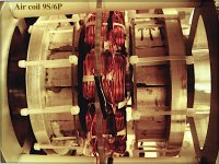
Air core axial Halbach..jpg
https://pdfs.semanticscholar.org/96e7/cbb78f65cbfa8df6c1b3a050aeac3c1bbd05.pdf

The biggest problem of using this design for a bike is probably the motors thickness,.. but, just thinking out loud.
 
APL said:
The overall diameter of the motor is missing, but from the r1 and r0 values i figure it to be 4".. or 5' overall. 9S/6P and
at 60v she spins 1k - 1.2k rpm to get 750w of output.

The biggest problem of using this design for a bike is probably the motors thickness,.. but, just thinking out loud.

The outer diameter of the magnet ring is given at 4" so I would guess that the actual outer diameter of the machine would be somewhere between 5" and 6". I am not proposing this as a design for an ebike only a good example of the application of design equations to a real world motor.

APL said:
The next big mystery to solve is the minimum iron needed before saturation at a given current for iron cores. Still kind
of a blind spot for me. Once thats done, I think we can get much closer to proper motor design. (Novice DIY)

That aspect of design is covered on pages 3 through 5 but it is a lot to get your head around that's for sure.

APL said:
If the diameter and internals are doubled, I assume that the rpm would be halved, and the torque would go up?

As it happens with axial flux motors power increases with the cube of the radius and obviously torque increases in proportion to the radius. The product of torque and angular velocity is power so as the designer you get to decide how fast your motor will spin with a given line voltage. In equation #13 the parameter that dictates the maximum angular velocity is Ⲱe. So your motor has 10 pole pairs and to calculate Ⲱe you choose an maximum rpm and convert that to rad/s and multiply by 10. Plainly there are practical limits since you can't realistically have less than one turn per tooth and current carrying capability and wire diameter dictate a practical maximum.

At the end of the day since your motor is designed for mid drive you have a lot more scope for Kv variations because you can choose to translate motor rpm to rear axle rpm in any way you choose.
 
No, I know you weren't proposing it, I should have made that more clear, sorry. I'm personally exploring the possibility.
We've been in and out of air coil design motors a few times in this thread, and it always seems to come down to low
end torque, or muti stator construction.

This one is closer in design to the current motor I'm making,.. using a single stator disc, trapezoid coils, and the added
Halbach PM's, eliminating back iron. So I was taking some time out to day dream a little about it.

I keep looking at air coil motors, because making steel cores is such a pain, and theres the potential for lightness, but
it's a trade off for magnet problems, and low end torque issues, it seems.
 
Tooth volume design is a tough one mathematically. But it mostly follows suit to the other basic motor parameters at first.
Like coil pitch, coil turns, and wire size, etc. It can only take up so much space in the area thats left.

Still, I guess, how much of that fill is necessary for the current being used is what I'm interested in. One can always remove
some material through drilling or machining. The papers are full of math and formulas, but never seem to address it
in the way I'm looking for. I guess it comes down to experimenting, although FEMM is probably the key.

Mostly my own curiosity though, since I'm always trying to find ways to make the motor lighter. If I can lose a mere 10g on
one core, it's equal to 360g for all of them. Close to a pound.

Heres another axial design paper, the longest I've seen yet, but with understandable language. I don't expect anybody to
read through it, just maybe look at the contents page. But it worth archiving here. (2005)

http://web.mit.edu/kirtley/binlustuff/literature/electric%20machine/designOfAxialFluxPMM.pdf
 
Cool work you're doing.

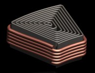
Would a "spiral-wound" stator core be beneficial? The axis of the spiral core would match the winding. Seems like it would be "easy" to make one.
 
I'm not sure what your meaning of 'spiral wound' stator core is,.. maybe if you could provide a visual of some kind?
 
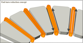
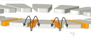
Speaking of different windings though, I had this thought the other day for reducing end turns. Can't say that I've ever
seen it used anywhere, so theres probably something wrong with it.

Some of the problems I can see are that, since one coil affects two cores, it would have to be wired in series, ABC,
ABC - ABC, so there wouldn't be any core groupings for balancing. Might not be an issue for slow speed motors though.

Might have cooling issues as well. Just another idea from the APL twilight zone. :)

End turn concept..png

See anything wrong?
 
The two coil sides cancel. Need area between the conductors carrying current in opposite directions.
major
{edit}
The method shown nets zero current per slot.
 
Ah... it's that pesky north and south again. I think this way 'all' the cores have to alternate between north or south at once.
Well, back to the drawing board.

Same direction..png

At least I finally figured out how to draw coils in CAD.
 
"Please excuse the crudity of this model as I didn't have time to build it to scale or paint it." - name that movie

This is what I mean by "spiral wound core". I would think it would be better that the cast powder cores and maybe easier to make than a traditional laminated core. It's probably very similar to how prismatic battery cells are made.

core_spiral.jpg
 
Thanks Gordon, excellent graphics! :thumb: Now I see what you mean. That would be nice, if it could be done, but there
are some problems. The laminations should all go from left to right, and not vertically, if it's going to be most
efficient. And the silicon steel used for lamination material is very brittle, and doesn't wind very well at all.

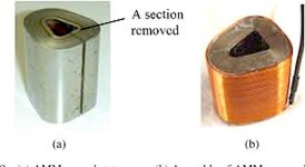
However, that being said, there are examples of your design being used with amorphous material with good success.
Hitachi has been experimenting with this for some time now and has achieved very high efficiency motors. (94% E.)

Amorphous wound core 1.jpg

Even though the greater majority of the material is wound radial, it still works quite well, although I see that the newer
designs are going back to all horizontal stacks.

I would love to try it as well, but as often the case, the availability and expense of the material is prohibitive.

More on amorphous core use; https://ieeexplore.ieee.org/stamp/stamp.jsp?arnumber=7933111
 
It brings me back to a question that has been nagging me for a while,.. seeing cores like this. I've always wondered, just
how important the 'center' of the core is to axial motor operation.
 
APL said:
It brings me back to a question that has been nagging me for a while,.. seeing cores like this. I've always wondered, just
how important the 'center' of the core is to axial motor operation.

It's really the CSA, cross sectional area, which is important to keep the flux density below saturation of the core material. If you're under the saturation level by sufficient margin, the center would be logical place lose material as to keep magnetic circuit paths shorter. But then why not make the tooth smaller and wire shorter along with it. There are some examples of wound field DC motors having split poles with space in the center. Mostly older stuff.
major
 
If there's a hole in the core then it will take a larger core to get the same flux. Larger core will take more copper to wrap around, so more resistance losses and more copper weight. There's a reason you avoid non-solid cores.
 
Having a larger core means more lenght of copper to achieve the same turn counts so more resistive loses, I agree with that, but it also means linking the flux of a larger magnet more efficiently (shorter flux Line) so more flux passing through overall. It all come down to a another compromise we have to make ?

Envoyé de mon Redmi Note 3 en utilisant Tapatalk

 
I suppose normal stator steel could be a problem winding (bending) it to core shapes. I happen to have some .001" thick Metglass laying around, it's like aluminum foil.

I was wondering about the direction of lamination and if it effects anything. Is there math somewhere that explains how? My impressions are that normal stators are made with single plate laminations is for manufacturing convenience not necessarily optimal performance.

I did find a YT video that showed a "spiral wound" stator (not just cores) being made from a continuous spool of thin steel, it was getting the wire slots stamped out as it went.

Search YT for "axial flux stator lamination manufacturing process video for disc motor and axial flux motor"

Also found another amazing stator making machine under "Stator Lamination Slinky Spiral Winding Machine"

Doesn't particularly help the DIY guy, but interesting.
 
Back
Top