dnmun
1 PW
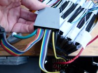
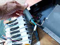
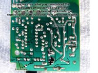
you don't know there is anything wrong with the BMS. it is functioning normally now. it is turned off because the one cell is so low. it has prevented all the other cells from overcharging so it is doing what it is supposed to do.
the top cell, #15 which you call #1 is still at 2V? you were not able to charge it up with the cell phone charger?
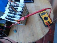
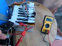
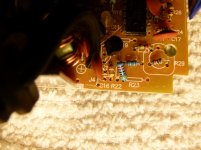
you can measure the voltage right on the terminals of the battery cells and that is where you have to use the alligator clips to attach the cell phone charger.
charge up #15 then let it settle, if it drains down to 2V again then you will have to open the BMS to see if the BMS is draining that one cell down, but first you gotta get the cell phone charger and clip it onto the terminals of that cell and charge it up. i think it will turn on the BMS as soon as you can get charge into it but you wanna charge it all the way up like all the others at 3.9V. but not more. you do have to watch it like a hawk after it climbs above 3.55V.
the top cell, #15 which you call #1 is still at 2V? you were not able to charge it up with the cell phone charger?
you can measure the voltage right on the terminals of the battery cells and that is where you have to use the alligator clips to attach the cell phone charger.
charge up #15 then let it settle, if it drains down to 2V again then you will have to open the BMS to see if the BMS is draining that one cell down, but first you gotta get the cell phone charger and clip it onto the terminals of that cell and charge it up. i think it will turn on the BMS as soon as you can get charge into it but you wanna charge it all the way up like all the others at 3.9V. but not more. you do have to watch it like a hawk after it climbs above 3.55V.