Battery cell pouch

dnmun said:
you can either short it with a wire or just replace it with a wire. same difference since it will still be zero ohms.

[(63ohms/1881ohms) + 1] X 54V = 55.81V

but that is just an estimate, it really should be the ratio of the resistance of the (1881-63) out of the total when you remove the resistor. but i don't have that total, so i just guessed.

it would be interesting to see what happens when you jumper over that resistor, to see what the voltage ends up at.

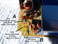
I did as you said, used a jumper to by pass the resistor R29 at ~63 Ohms. First, I did unsolder one of its lead. The voltage output with the jumper is 56.5V. It seem to work as you said. And I assume it is very good? Do I keep it this way or replace it with another resistor? Thanks a lot for all your help. Regards JJ
 
sounds right. i was just guessing because i didn't account for the resistors in the top part of the resistor divider. but zero ohms is 56.5 and 63 is 54.7 so if you get the equivalent resistance to around 50 ohms the voltage will be 55V. for 40 ohms it will be 55.4V.

when you combine two resistors in parallel, the equivalent resistance of the two resistors is Req=(R1xR2)/(R1+R2).

to make an Req of 40 ohms, and using R1 as the 63 ohm resistor (63R2)/(63+R2)=40 ohms. solve for R2. 23R2=(63X40). R2=109 ohms.

so if you add a resistor aound 109 ohms in parallel with the 63 ohm resistor, it will end up putting out 55.4V

any of these work to force the pack to balance. resistors come in standard values too so something in that range is ok to boost the charger voltage up just a little bit.

and you learned a little electronics to boot.
 
dnmun said:
...

when you combine two resistors in parallel, the equivalent resistance of the two resistors is Req=(R1xR2)/(R1+R2).

to make an Req of 40 ohms, and using R1 as the 63 ohm resistor (63R2)/(63+R2)=40 ohms. solve for R2. 23R2=(63X40). R2=109 ohms.

so if you add a resistor aound 109 ohms in parallel with the 63 ohm resistor, it will end up putting out 55.4V....

Sorry to seem dumb but, which one would be R2? Is the R20 (next to R29) or the top resistor (just above R29, slightly to the left)???

I would guess it is the one next to R29. And it needs to be changed to a 109 Ohms. Am I correct? Tomorrow, I am out to buy the 109 Ohms resistor. Thanks. Regards JJ
 
i doubt if there is a 109 ohm resistor, the standard values will be close, maybe you will find a 110R, 100 ohm is common, but the R2 is the resistor that is soldered in parallel to R1 which is your R29. so the equivalent resistance of the two in parallel gets you to about 40 ohms.

110 is brown brown brown
 
dnmun said:
... R2 is the resistor that is soldered in parallel to R1 which is your R29.... .

Hi: I'm still not clear and need to confirm, which resistor is the parallel one (R2) "A" or "B" see image below?
 

Attachments

  • ParallelResistor.jpg
    ParallelResistor.jpg
    90.1 KB · Views: 1,237
the idea is to change the R29 value to 40 ohms so the output voltage ends up at the 55.6V level or whatever i estimated back there.

since you have a 63 ohm resistor there already, R29, you will add a resistor in parallel, 109 ohms (100 or 110 ohms is most likely value you will find), in order to make an 'equivalent' resistor of 40 ohms.

the Req value is determined by using the current value of R1, 63 ohms, and solving for R2.

Req=(R1XR2)/(R1+R2)

40 = (63 R2)/ (63 + R2)

40(63 + R2) =63 R2

2520 = 23 R2

R2=109.57 ohms.

or you can find a 40 ohms resistor, not likely to find, but 47 ohm is common, and use that instead of the equivalent resistor.

or you can add what you want in order to adjust it to a voltage you like, or maybe just use a resistor close enuff if that is all you can find.

i have bunches of little tins and plastic display boxes full of resistors i unsoldered and saved from old dead electronics and chargers and tvs that i use for stuff like this. except it takes so long to go through them looking for a specific value. but you learn to read color codes that way too. or i do anyway.
 
Zippedy said:
This thread is 'awesome'.
I salute both dnmun for taking the effort and Milou for taking the plunge.

The salute belong to "dnmun" (amazing guy). I am only plunging in without knowing how to swim. I have taken so many gulps of water I feel like I am drowning (just one more stroke...).

dnmun said:
...since you have a 63 ohm resistor there already, R29, you will add a resistor in parallel, 109 ohms (100 or 110 ohms is most likely value you will find), in order to make an 'equivalent' resistor of 40 ohms.

...

i have bunches of little tins and plastic display boxes full of resistors i unsoldered and saved from old dead electronics and chargers and tvs that i use for stuff like this. except it takes so long to go through them looking for a specific value. but you learn to read color codes that way too. or i do anyway.

Hi dnmun: Thanks for your proposition but, do not bother looking for the resistor on my account. I was able to get a 110 Ohms, 1/4 watt resistor from Fry's Electronics. Did I tell you I am color blind??? I also need glasses to read. As a result, I have someone read out those tiny resistors for me!

I feel completely embarrassed. After some relief from my regular job I got some time to look over-and-over your postings and "parallel resistor soldering" definition. It is not the math (I understand solving equations) it was locating where to solder? I now realize, it needs to be "piggy-back" to the R29 resistor. I was thinking "parallel" to be the same axis and there were two other resistors in that condition. Now, I am back on track to get it done these coming days. thanks a load for your persistence to guide me on my dark path. Regards JJ
 
well, everybody gotta start some time. i think most people avoid making themselves learn it by kinda doing homework like stuff because they think it is so impenetrable. you can think of current like plumbing too. wikipedia actually has readable stuff on electronics too. like how transistors work and other useful stuff.

but this all started because the cell got so discharged, doing all this is just to make your charger put out a little extra voltage so the BMS can balance the pack more easily. this is what ping does now too.

if a lot of the cells pump up to 3.85V ahead of this one that doesn't show as much voltage when it is charged, then it may not store as much charge as the other cells and limit the capacity of the pack. so the extra voltage lets the high cells shunt the current while this cell can be guaranteed to get juice when they are full past 3.65V.
 
Hi dnmun: I got the resistor soldered and I tested the voltage coming out as 55.4V as the math predicted. My soldering technique is sloppy (bad iron) but, it got it done. As usual, thanks a ton for the help. Regards JJ
 
55.4V/15=3.69V for each cell. if you watch the voltages on the cells, you will see that some are higher than this and some lower.

those first few cells you had discharged so badly originally will always be lower i expect, so the extra voltage helps them get charged too.
 
Nice work dnmun. I'm beginning to wonder if my new CI-Power (looks just like the V-Power) 48v,20aHr pack, has the same BMS issue. The pack only delivers 18.65 to 19aHr (some nursing required for the latter) per run. After sitting for an hour, after use (and before charging) it has an indicated recovery voltage of 50.7V. Also, after a full charge and a reading of 59.9V, 24 hours later it reads 56.6V. I noticed you mentioned Ping,my Ping 48V, 15aHr pack delivers 16aHr+ all the time, great pack.

Question: Should I be concerned, further investigate, or leave well enough alone? Also, could you direct me to a thread that further explores battery pack issues like this and more info on BMS types and configurations?
Thanks!
~don
 
best way to understand your pack is to measure the cell voltage while it is charging. your charger voltage seems high like ping does, enuff to be certain the low cells fill up also. that's what we were doing for milou.

the Vpower packs never delivered advertised capacity imo.

if your pack is built up like the Vpower from the little cylindrical cells, you have to worry about shorting of the metal strap that ties each row together in parallel at the point on the end where the end of the strap extends out beyond the end of the last case on the anode end. the positive end of the cells.

the case can short that strap when the strap is jammed down onto and through the thin plastic insulation covering the case and that shorts out the entire row. fire hazard and kills the pack.
 
I'm back. I took my first long ride on the motor scooter.I live in a mountain area with lots of short rolling hills. The scooter really struggles up hills. I got to 2 miles and the motor just quit (stopped, no juice going to it). I started to walk it back home (2 miles back). After about 15 minutes the motor started again but quit shortly after. Twice this happened until I got nothing at all. When I got home the battery was at 42.5v.

Why does the motor just quit? I know it struggles up the hill yet, I am not heavy weight. The motor does not seem hot (touched casing with my hands). The scooter is rated at 500W 48V. 15amps. I am really surprised by the very small mileage (2 miles) I get and wonder if any electric transport is worthy of trying???
 
Hi Guys: I have recharged the battery and went out again riding. The same happen, after about 2 miles the scooter shut down. I walked it back home and checked the battery. Each cells were reading within 3.1 to 3.3V at a total of 49.5V. The battery was not hot and no burn marks. Maybe the battery had time to get its breather? When riding the throttle is quick to react but, there just seems no real power (oomph) on any slight hills. I am not sure what is going on??? Regards JJ
 
Milou: Remember cell #15? The one that got down to 0V? Sounds like it did not recover (as I suspected earlier on). Even though you were able to bring its voltage back up to normal, it appears that the cell has lost most of its capacity and is triggering the LVC (low voltage cutoff). Do you still have access to the balance leads? Bring the voltmeter with you the next time it happens and check the voltage of each cell. I suspect that the voltage of cell #15 is way lower than the rest.

May be it's time for you to do a capacity check at home. It's much quicker and it's also much easier to identify the offending cell.
 
Hi: I did another try till the bike went dead and checked each cell pouch immediately thereafter. The only low cell was "my number 15". It read 2.90V while all others were at 3.2V. I am surprised the whole thing shut off completely very so little voltage drop.

How does one do "capacity check" with one of these packs or individual pouches? Thanks for the help again, again, and again... . Regards JJ
 
the cell voltage jumps back up to what you measured at 2.9V after it shuts off for LVC under load. for the ping pouches under light load they jump back up to 2.7V then climb up a little more to 2.8-2.9V over a few minutes, from the 2.1V LVC where you stopped the discharge.

to measure capacity you have to find a dummy load. either lights or a space heater. i use these oil filled delonghi radiators to discharge a battery into in order to measure capacity.

but first you have be certain that each cell is fully charged to 3.65V. then discharge it through either a watt meter or cycle analyst or you can discharge through your voltmeter set to the 10A range and measure the current as it is discharged.

record the current reading, to see how many amps are discharged until the individual cells drop to the 2.1V level.

so to do this, you need two voltmeters. one to record the current and one to record the voltage. using a wattmeter is easier since it records the amp hours automatically. measure time and current accurately.

when you are discharging the pack, your #1 cell will reach the 2.1V level first it appears. record the time, multiply time by the average current and you have the amp hours or charge released by the pack.

in order to continue the discharge to find the capacity of the other cells, you use a single cell charger to put some charge back into the cell that got to the LVC first, just enuff to complete the test, and then you continue the discharge until the next cell reaches LVC, stop and record the time, multiply by avg current for amp hours Ah, add a little charge back to that one to continue to find the next lowest cell in capacity, and so on until you are satisfied with knowing how the pack works.
 
Agreed.

But if the goal is just to ascertain that cell #15 is the bad guy, I would just do a capacity check on that cell: Charge it back up to [3.60 - 3.70V] range using that cell phone charger (it should not take long since its capacity is presumably very low). Discharge it at [3 to 5A] rate. If it's the bad cell, voltage will drop to 2.0V within an hour.
 
dnmun said:
best way to understand your pack is to measure the cell voltage while it is charging. your charger voltage seems high like ping does, enuff to be certain the low cells fill up also. that's what we were doing for milou.

the Vpower packs never delivered advertised capacity imo.

if your pack is built up like the Vpower from the little cylindrical cells, you have to worry about shorting of the metal strap that ties each row together in parallel at the point on the end where the end of the strap extends out beyond the end of the last case on the anode end. the positive end of the cells.

the case can short that strap when the strap is jammed down onto and through the thin plastic insulation covering the case and that shorts out the entire row. fire hazard and kills the pack.
As the voltage levels are okay (true?) I going to assume you're saying keep a wary eye out ("worry about") for heat or low voltage levels, if I experience a crash or other possible "pack damaging" event. I currently carry the CI Power (Vpower copy) in a backpack so it never really gets pounded by road shock or anything. Is this line of reasoning correct? Am I good to go? Or, is the concern high enough that I should pull the duct tape off and examine/mod this pack (bought new in Oct.)? Thanks for your help!
 
the critical spots are the corners or edges of the pack where that strap across the anode end of a row ends.

if you can keep it from dropping or hitting something that would cause that strap to cut through the insulation on the case then you are safe.

the problem with all these packs wrapped in tons of tape is that you cannot see anything, but if it shorts then it may be hot enuff to melt a hole through the tape.

in the pack i have that was given to me when it arrived dead here in the US, it had shorted at the factory during assembly, so there was no tape around the spot where the strap shorted. they finished assembling the pack and wrapped it with tape without ever seeing the short. the end of the cells were crushed a little too. shoulda been obvious imo.
 
dnmun said:
... when you are discharging the pack, your #1 cell will reach the 2.1V level first it appears. record the time, multiply time by the average current and you have the amp hours or charge released by the pack.

in order to continue the discharge to find the capacity of the other cells, you use a single cell charger to put some charge back into the cell that got to the LVC first, just enuff to complete the test, and then you continue the discharge until the next cell reaches LVC, stop and record the time, multiply by avg current for amp hours Ah, add a little charge back to that one to continue to find the next lowest cell in capacity, and so on until you are satisfied with knowing how the pack works.

SamTexas said:
Agreed.

But if the goal is just to ascertain that cell #15 is the bad guy, I would just do a capacity check on that cell: Charge it back up to [3.60 - 3.70V] range using that cell phone charger (it should not take long since its capacity is presumably very low). Discharge it at [3 to 5A] rate. If it's the bad cell, voltage will drop to 2.0V within an hour.

Hi:
I have been reading about "how to battery-capacity-testing". A lot of unknown Mumbo-Jumbo. Given the battery voltage is not constant! When you attach the load, the battery voltage will slowly drop as the battery drains. Is there a way to use a constant-current load. Where such a load will remain constant regardless of the battery voltage (drawing a constant current)?

I assume I will put the load with clips to the cell pouch or battery pack? I bypass the BMS sensor. Else, how do I put the load to the three prongs from my battery pack (see attached PDF file)?

On another note: I already know my battery pack does not function as it should. Now I am suppose to find out why and where? When I find the problem with one of the cells, I will need to replace it. Given that the other good cells have been somewhat used, I would be putting a new cell with them. It appears there would be a balance issue again??? Not only the capacity but also the cell dimenssions (I have not yet found an identical replacement to the cells I have). Would it not be better off to change the whole battery pack as new?

Regards JJ
 

Attachments

  • Battery Pack.pdf
    33.3 KB · Views: 55
Back
Top