Battery build & Controller Upgrade

On that note.

I have a plan for batteries for an e-bike my son wants changed out (it has a 10AH pack and he wants the 20 like his other ride has) I had a few long conversations with a couple Sparkies, and they eventually agreed that you can in fact have you unit split between 2 cels with a single BMS, it is gonna have cross connections in 00/2 and the output feed is gonna stay right where it is at now. I am gonna build this and then do a synthetic load test. Once again, because fire down below sounds great in a war movie, but not for your ebike.

I am not endorsing these statements, I am saying I am going to test the theory, and I don't think these chaps are wrong, i just have not seen anyone actually do that on a bike so far.

More when I have it.
 
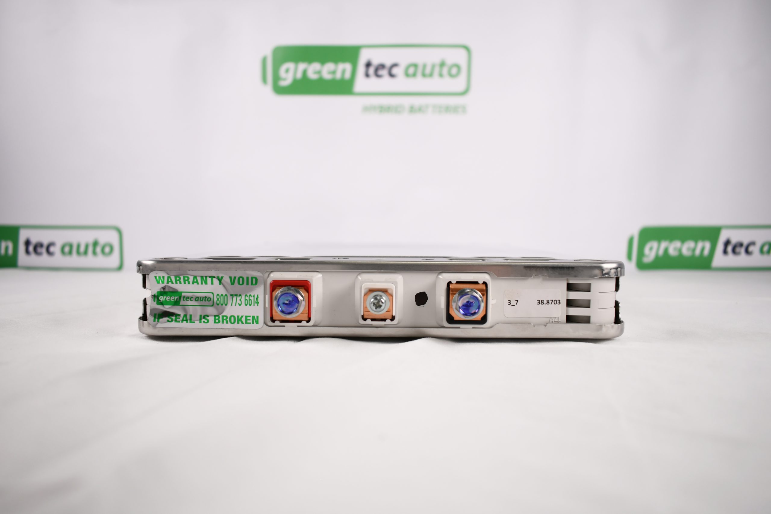
I decided to go with the Nissan Leaf modules for my battery pack. (20S1P) 72v 40Ah.
ANT BMS 20S 340A / 850A peak.
Kelly KLS7250ND 72v 190A Continuous / 360A Peak
My motor is a 3000w hub motor but I might upgrade later on in the future.
 
Last edited:
Where are you getting the Leaf modules?
Greentec in the U.S has the Leaf modules. I'm getting them shipped from Kansas City. It's expensive but the battery pack will still be cheaper in the end rather than the battery pack from Amazon.ca (that doesn't say info on the cells or the bms.)
 
Last edited:
After I get the bms, controller and other items delivered, put on the bike and working...

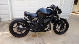
I would like to think ahead and dream a little. I plan on buying another 10 Leaf modules at the end of this riding season to add more capacity. I was thinking about selling my bike, buying a Honda cafe racer or something like that, and building a new bike. However I don't think I am capable. I am also too nervous of even purchasing from China and dealing with the potential shipping issues. Also the cost will be too much. This really leaves me with only one option. One I thought about and said no but didn't look at pictures until today. I wondered what a ninja or a gsxr sport bike would look like modified so I put it in the google search. I found some bikes that looked really good, some that looked really bad.. and this one similar ones that looked good but also like something I was capable of doing. Just looks like cutting, welding, grinding, painting. I can do those things! lol

I know I said at first that I couldn't live without the fairing kit.

A little longer tail end for me than is shown in this picture.. but something like this would be cool. I actually really like the look of this.

The fairings sure do give it that "fast" look though and would be missed (even though some screw holes cracked and the fairings don't all tuck in 100% neat anymore around the headlights)

Obviously there would be a big ol' battery box in there instead of the motor & I don't have a 3D printer or the skills with fiberglass to do anything really nice. So cutting and welding metal will have to work. I think it would be really cool though.

I was already thinking about changing the lights on the bike since the ones that came on it are not very bright. I don't mind the looks of a simple round light mounted to the fork tubes.

I'm still debating it. I would love to get more capacity for longer rides in the future. Something like this would be my cheapest option.

I just don't know. Do you guys like this kind of conversion for a sport bike like a Suzuki GSXR or Kawasaki Ninja?

Anyone have any opinions they want to share I'm all ears!

Would be a cool little project to take on.. If I can get passed this first task of getting the new battery/bms in, and controller upgraded on my current set up. I might try something over the next winter.

1712104220532.jpeg
 
Last edited:
After I get the bms, controller and other items delivered, put on the bike and working...

I would like to think ahead and dream a little. I plan on buying another 10 Leaf modules at the end of this riding season to add more capacity. I was thinking about selling my bike, buying a Honda cafe racer or something like that, and building a new bike. However I don't think I am capable. I am also too nervous of even purchasing from China and dealing with the potential shipping issues. Also the cost will be too much. This really leaves me with only one option. One I thought about and said no but didn't look at pictures until today. I wondered what a ninja or a gsxr sport bike would look like modified so I put it in the google search. I found some bikes that looked really good, some that looked really bad.. and this one similar ones that looked good but also like something I was capable of doing. Just looks like cutting, welding, grinding, painting. I can do those things! lol

I know I said at first that I couldn't live without the fairing kit.

A little longer tail end for me than is shown in this picture.. but something like this would be cool. I actually really like the look of this.

The fairings sure do give it that "fast" look though and would be missed (even though some screw holes cracked and the fairings don't all tuck in 100% neat anymore around the headlights)

Obviously there would be a big ol' battery box in there instead of the motor & I don't have a 3D printer or the skills with fiberglass to do anything really nice. So cutting and welding metal will have to work. I think it would be really cool though.

I was already thinking about changing the lights on the bike since the ones that came on it are not very bright. I don't mind the looks of a simple round light mounted to the fork tubes.

I'm still debating it. I would love to get more capacity for longer rides in the future. Something like this would be my cheapest option.

I just don't know. Do you guys like this kind of conversion for a sport bike like a Suzuki GSXR or Kawasaki Ninja?

Anyone have any opinions they want to share I'm all ears!

Would be a cool little project to take on.. If I can get passed this first task of getting the new battery/bms in, and controller upgraded on my current set up. I might try something over the next winter.

View attachment 350396
Roadsters always look really nice when they have an internal combustion engine. Remove it, replace it with a box and it doesn't look nearly as good. That's the biggest issue with this kind of ev conversions on roadsters, they will look crappy if the battery box isn't very creative/original.

I wanted to do that exactly this at first with my red bike, but decided against it because of this reason. Plus I thought it would be fun to try and make something very different, for the sake of experiment.

Anyway, as someone who did both of these builds (sportsbike and roadster), I recommend to keep the fairings, make em look nicer and focus on all the other stuff. It'll be much easier for a first build and it has a higher chance of looking better/higher quality.
 
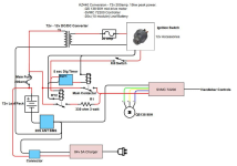
I found this great schematic on the forum. It is very similar to what I will have going on soon in my E-moto.
I have to put in a new fuse but I am not sure if a 200A main fuse will be enough.
Can anyone help me figure it out? I heard from a friend that the 200A fuse might blow with just plain riding and it makes sense. It should only blow in the case of something extreme, I get that. 200A does seem low for my application. My controller continuous amps are almost 200 (190A) but it can go up to 360A for 1min, and probably spike a little higher than that even. I should get maybe a 400 or 500A fuse then right?
Maybe others can benefit from this.
Thanks everyone.


1712235984911.png
 
Last edited:
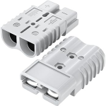
The connector I want to use is good for 350A but only 2/0 AWG copper wire though.

1712264513954.png

2/0 AWG copper wire is good for 200A .. Maybe I have to find a connector that can take heavier duty wire or something that doesn't seem like it will be enough.
 
Last edited:
I have to put in a new fuse but I am not sure if a 200A main fuse will be enough.
Can anyone help me figure it out? I heard from a friend that the 200A fuse might blow with just plain riding and it makes sense. It should only blow in the case of something extreme, I get that. 200A does seem low for my application. My controller continuous amps are almost 200 (190A) but it can go up to 360A for 1min, and probably spike a little higher than that even. I should get maybe a 400 or 500A fuse then right?

There's a number of good fuse discussions around the forum with details, but basically you need a fuse rated to protect your wiring, etc., against a fire in case of a short circuit in that wiring "downstream" from the fuse.

Really, it's protecting the whole system from a fire that could occur from teh current the battery can supply in such a situation.

Because of that you normally want the fuse at the battery terminal itself, so it protects against a short in the most system wiring/etc as possible.


The fuse rating would need to be higher than the highest possible voltage ever present in the wiring it's for, so it will not arc across and continue flowing current when it blows.

And higher than the highest possible normal continuous current the system will ever see.

If you expect very short peaks of current higher than that, it's ok as long as your fuse can handle that much for that long. Each fuse has a spec sheet on the manufacturer site that shows current vs time for how long it will take to open (blow).


I haven't checked out the link yet, but this post today
has this:
I couldn't see many references to fuses for higher powered emoto builds on Endless Sphere so I'll add a link to the fuse I selected for my build. It's from a marine manufacturer and built by Bussmann here: Class T Fuse - 400 Amp - Blue Sea Systems

The fuse and fuse block are rated to 160V DC.
Sizes range from 225 to 400A and have a 20kA interrupt current at 160V DC which should fit the requirements of most builds.

I also found a super useful link from Eaton Bussmann for sizing fuses for EVs based on short term pulse usage here: https://www.eaton.com/content/dam/e...ehicle-application-guide-br132016en-en-gb.pdf

Its is quite large but there is also a smaller fuse holder for builds that are more constrained on space. The fuse terminates on a 150mm2 bus.
Image for size reference:

View attachment 350513
 
Last edited:
The connector I want to use is good for 350A but only 2/0 AWG copper wire though.

View attachment 350499

2/0 AWG copper wire is good for 200A .. Maybe I have to find a connector that can take heavier duty wire or something that doesn't seem like it will be enough.
The anderson SB series has versions that go higher than that, and can hold bigger wires....they're just bigger housings and contacts. :)

The SB350 will handle 500A and bigger than 4/0 wire, but it's kinda big, at over 4" long and almost 3" wide for the housing, over 7" long for a mated housing pair. .
The SB® 350 is the largest connector in the series withpower capabilities up to 500 amps with a 350 mcm wire.Wires ranging from 1/0 to 350 mcm (53.5 to 185 mm²)fit into the one piece housing available in standard PC ora chemical resistant PBT/PC blend. Silver plated wire orbusbar contacts minimize electrical resistance whileoffering supreme durability and reliability.• Up to 350 mcm (185 mm²) Wires Allows UL rated currents up to 500 amps


The SB175 is only about 3" long x 2" wide, but only rated to about half the SB350 current, and only 2/0 wire, I think..
 

Attachments

  • ds-sb350[1].pdf
    1 MB · Views: 2
  • DS-SB175[1].pdf
    1.2 MB · Views: 1
Last edited:
4/0 AWG Copper wire is good for 230A so I will try to limit my power to around that. I'm not trying to see wires or anything smoking. I'll get one of those 400A fuses to protect the system from anything crazy.
I don't even know what the next measurements of wire are. Kcmil.. Sounds expensive lol.
 
Last edited:
4/0 AWG Copper wire is good for 230A so I will try to limit my power to around that.
In my experience 4 gauge will take much higher bursts of current without any issues, have pushed near 450 amps for short bursts and it got just barely warm. The important bit to remember is that while might be rated at 230 amps you dont know how they obtained that rating. What I mean by this is that its important to look at for how long will it sustain that figure and to what temperature limits and such. As an example it might be rated for 230 amps for one hour up to 90c.

To clarify further the most important thing to pay attention to is temperatures when it comes to controllers/wiring/motors/whatever as heat is the enemy, its what damages and kills components. As an example Ive used 8 gauge for my main pack discharge on one of my older projects with peaks around 250 or so amperes without much issue, while sure it was well out of for what it was rated no damage occurred as it got plenty of airflow which didnt allow heat to build up (and also because it was running maybe only 70-80 amps continuous).

Also another connector that you might want to consider is a qs10, its the bigger brother of qs8s and has nice antispark if you dont have a precharge resistor somewhere else down the line, main advantage is that is much smaller than the andersons but with the disadvantage of having to solder instead of crimping...oh and its also waterproof so thats a bonus I suppose.
 
This it will give you an idea of the current that will overload a 4/0 copper wire and how long it would take to reach the max tempature.
Later floyd
 
BTW, unless you have a requirement to be able to very quickly and easily remove the battery (not usualy possible with big batteries like those on MC's, as they are often built into the bike pretty solidly) and if you have a contactor setup, or some other switch in the battery circuit already, you don't really require a connector.

You can just crimp ring terminals to the battery output wires, and bolt it directly to whatever comes after it. If you do, I recommend making the cables unequal length, so that if they happen to hang off while you're working with the battery or system they cannot touch each other's ends, and cover the ends with hard plastic or thick marine heatshrink over all of the end except the actual ring, making it even harder to have an accidental contact.

If you have the fuse in the battery cable, at the exit of the battery, you can use ring terminals on the cable to and from that, too.
 
1712318954456.png
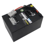
The old battery looked just like this ^

I have to remove the fairing on the one side of the bike, but I didn't weld the box that the battery goes into, on to the bike. The battery box has a side panel that can be unscrewed and taken off to put in/take out the battery. The battery wasn't mine I was borrowing it from a friend. I thought I was going to have to give it back so I built the box it was going in accordingly. Easy to access and take the battery out when needed.

There is an Anderson connector on the bike that the battery plugs into once it is put into the battery box on the bike.

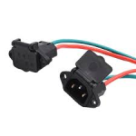
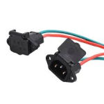
There is also a separate charging port on the bike which is a standard household plug type, male end. Looks something like this:
1712319994393.png

So I don't have to unplug the battery from the bike to charge it. I can plug the male end of the charger into the wall and the female end of the charger right into the bike.

There's also a heavy duty single pole breaker type switch on the bike. However I did not see a contactor anywhere. I don't really need one I don't think? The BMS can do the contactors job as well as the shunt so I don't plan on having either in the new system. I think it can also do the precharge as well. I was told it can do all of those things.

I do like the breaker type switch though I did use it. I think the BMS can do that too though. I might still utilize one. I liked it.

I'll take some pictures trying to show what I'm talking about/working with soon. I know it's probably harder to follow my explanation without seeing.
 

Attachments

  • 1712319975081.png
    1712319975081.png
    34.6 KB · Views: 1
Last edited:
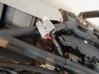
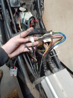
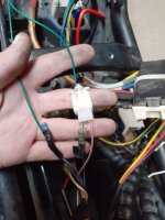
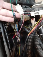
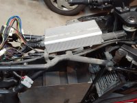
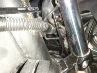
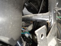
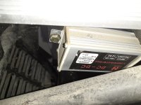
Photo dump.

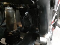
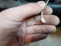
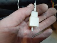
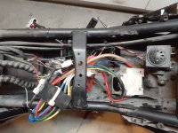
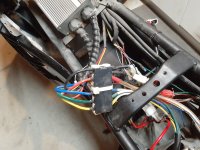
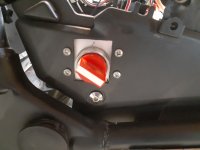
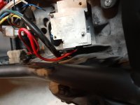
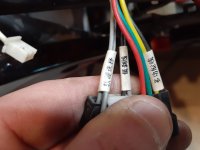
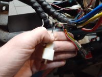
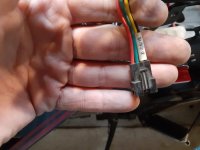
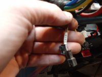
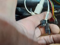
Those are the guts. There's more not connected than there is connected.. I'm joking but there are a lot of loose wires even one that is just cut! I took pictures of the disconnected wires and tried to include the labels. Sadly I can't read what it says they do.
I'm a little scared looking at it all again but I hope I can sort it out. I haven't completely stripped the bike down yet. I plan on stripping it down soon to see everything in the front end that I couldn't today.

There is a switch the original owner had to switch batteries, as he had 2 in there. I never used it or bothered with removing it. It's just been there.

There's a couple pictures that don't look like much but they are the front end under the speedometer. I didn't take the front headlight assembly off or the front fairings yet. I just wanted to show the pictures of the wires. A lot of it is probably the lights, horn ect. I will be able to tell which wires go where much better when it gets a little bit warmer out. Hands were freezing today the weather has been on and off lately, couple weeks ago it was beautiful outside and this morning it was snowing.
 

Attachments

  • 20240405_101208.jpg
    20240405_101208.jpg
    3.4 MB · Views: 5
  • 20240405_101348.jpg
    20240405_101348.jpg
    3.1 MB · Views: 5
  • 20240405_102144.jpg
    20240405_102144.jpg
    1.5 MB · Views: 5
  • 20240405_102151.jpg
    20240405_102151.jpg
    1.3 MB · Views: 5
  • 20240405_102201.jpg
    20240405_102201.jpg
    1.7 MB · Views: 5
  • 20240405_102216.jpg
    20240405_102216.jpg
    2.8 MB · Views: 5
  • 20240405_102236.jpg
    20240405_102236.jpg
    4 MB · Views: 5
  • 20240405_102244.jpg
    20240405_102244.jpg
    4.1 MB · Views: 5
  • 20240405_102335.jpg
    20240405_102335.jpg
    4.1 MB · Views: 5
  • 20240405_101145.jpg
    20240405_101145.jpg
    2.6 MB · Views: 5
  • 20240405_101137.jpg
    20240405_101137.jpg
    2.8 MB · Views: 6
  • 20240405_100714.jpg
    20240405_100714.jpg
    3 MB · Views: 5
  • 20240405_100733.jpg
    20240405_100733.jpg
    2.9 MB · Views: 6
  • 20240405_100748.jpg
    20240405_100748.jpg
    3.4 MB · Views: 5
  • 20240405_100831.jpg
    20240405_100831.jpg
    1.7 MB · Views: 5
  • 20240405_100950.jpg
    20240405_100950.jpg
    2.4 MB · Views: 5
  • 20240405_101037.jpg
    20240405_101037.jpg
    2.4 MB · Views: 6
  • 20240405_101046.jpg
    20240405_101046.jpg
    3.7 MB · Views: 6
  • 20240405_101104.jpg
    20240405_101104.jpg
    2.5 MB · Views: 5
  • 20240405_101123.jpg
    20240405_101123.jpg
    2.4 MB · Views: 5
Last edited:
The connector I want to use is good for 350A but only 2/0 AWG copper wire though.

View attachment 350499

2/0 AWG copper wire is good for 200A .. Maybe I have to find a connector that can take heavier duty wire or something that doesn't seem like it will be enough.
You don't need those unless you plan on often removing the battery, don't bother. Just use some good quality lug terminals and bolt the wires.
I used these Anderson connectors on my scooter before, it was a waste of space and weight, I don't use them anymore.

2/0 AWG copper is good for 200A continuous.
Continuous means 27/7. In our application our bikes will only see these kind of currents for a few seconds, maybe minutes. So you really don't need to go for crazy big wires, 2/0 AWG is already much more than you'd need with a 200A controller. That's what I'm using and so far it seem to be just fine with 400+ Amps. In my opinion (but that's just my opinion), they should be able to tolerate more than 1000A for several seconds without any issue.
Look at the motor phase wires, they can take even more amps yet they are thinner. As long as your wires are at least as big as the phase wires you should be fine.
So yeah don't worry you can use AWG 2/0, no problem.
 
Last edited:
Photo dump.

Those are the guts. There's more not connected than there is connected.. I'm joking but there are a lot of loose wires even one that is just cut! I took pictures of the disconnected wired and tried to include the labels. Sadly I can't read what it says they do.
I'm a little scared looking at it all again but I hope I can sort it out. I haven't completely stripped the bike down yet. I plan on stripping it down soon to see everything in the front end that I couldn't today.
The only necessary wires to run the bike are the following, you need to identify them:
-throttle wires, usually 3 wires red/green/black
-ignition wire: one single wire, color may vary, it's the one that is linked to the key switch (or the alarm system), that's the wire you connect to the controller to switch it ON
-motor hall sensor wires, 5 wires, usually red/black/green/yellow/blue
-Motor phase wires: the big motor wires, green/yellow/blue
-Battery wires: Red/Black
At first I suggest you only focus on these ones, then once everything runs fine you can start adding the remaining stuff.

There's a couple pictures that don't look like much but they are they front end under the speedometer. I didn't take the front headlight assembly off or the front fairings yet. I just wanted to show the pictures of the wires. A lot of it is probably the lights, horn ect. I will be able to tell which wires go where much better when it gets a little bit warmer out.
Don't bother messing with these just yet, you can always do that later, keep it simple.
 
You don't need those unless you plan on often removing the battery, don't bother. Just use some good quality lug terminals and bolt the wires.
I used these Anderson connectors on my scooter before, it was a waste of space and weight, I don't use them anymore.
I will not be removing the battery often so I am thinking about taking your advice and using lug terminals to bolt the wires. Do you recommend bolting them directly together and cover it using heat shrink wrap?

Also, do you have a similar charging port on your bike? I really want to keep that.

I think that once I get things tidy in there it will be a lot better. Right now it is a mess. That switch for the dual battery is stupid I'm going to disconnect it when I redo the wiring, I wish it wasn't so horribly butchered. Could have used a proper hole saw.

I like the busbar (or whatever the correct term is) that joins the wires all nicely together in a case that is there I will try to reuse it if I can.

The first warm day I will get back out and remove some of the cable ties to loosen the wiring so I can see where exactly everything is going. I know where all of the wires you mentioned above are for the most part but I have to figure out which one is the ignition wire.

I'm looking at the wires and plugs that are on the Kelly Controller and it doesn't look like anything matches up with what I have on the bike. I will have to figure out what to do there maybe change the plug types or something I have no idea.

Other than that I am feeling a little better now. Thanks for the advice on the 2/0 wire it will save me some money.
 
Last edited:
If you want something smaller than the Anderson and do not want to plug it often , just take two QS10 plugs and take one of them for plus and the other for minus. The qs 10 can handle awg4
The wire ratings are all for continious operation 1 hour or more. You can not draw 400A for an hour from your battery. If your wiring is good for 200A continious, you can draw 15min 400A without overheating the wires. Or you also can draw 3 minutes 800A.

I use a 325A ANL Fuse rated for 80V in my scooter. Battery is 21S100Ah Li-NMC and the controller is set to 400A. Wiring is two times AWG5 in parallel.
The 400A will only be drwan during acceleration.
 
Last edited:
I will not be removing the battery often so I am thinking about taking your advice and using lug terminals to bolt the wires. Do you recommend bolting them directly together and cover it using heat shrink wrap?
Yes.
I used an hydraulic crimper to secure them, but it's an expensive tool. Before having it I just crimped the terminals with a clamp, then used a blowtorch and solder to make sure the lugs were really secured.
Also, do you have a similar charging port on your bike? I really want to keep that.
Yes, but mine is a bit bigger and can take more charging current.
You can use whatever plug fits your charger.

The first warm day I will get back out and remove some of the cable ties to loosen the wiring so I can see where exactly everything is going. I know where all of the wires you mentioned above are for the most part but I have to figure out which one is the ignition wire.
I suggest you to be patient and go step by step, first step identify the ignition wire, then wait to receive your controller.
Once you receive it, connect only the wires I mentioned. Then make sure everything works as intended.
Only then you can start working on removing the cable ties and improving the harness.
Otherwise you risk damaging some part of the harness and it will make troubleshooting a whole lot more difficult.

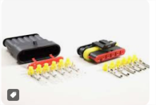
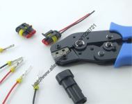
Also, I suggest you to purchase some waterproof connectors and the appropriate crimping tool for them. In my experience, 99% of the problems come from the shit connectors they use from factory. I changed all of them on my bike and haven't had a problem ever since. There are some nice youtube videos that explain how to properly crimp these things, it's very easy to do and it will save you so much trouble later.

Personnally I use this kind of connectors:

1712460881931.png
amd this kind of crimping tool:
1712460938506.png

Never had any issue with these, so I can definitely recommend.
 
I wonder if it is a good idea to get the BMS display and try to put it by the speedometer or something
Yes, the BMS screen is great, I've put it on all my vehicles and can't think of anything better.
The only downsides is that it's not a particularly beautiful screen and it is a bit fragile. Also it doesn't come with an enclosure so it's not always easy to fit in the bike, and making it waterproof is definitely a challenge.
But it shows every information you ever need and it has a backlight so it's easy to read even under sunlight.
 
I used an hydraulic crimper to secure them, but it's an expensive tool. Before having it I just crimped the terminals with a clamp, then used a blowtorch and solder to make sure the lugs were really secured.
I use a hammer crimp. Much cheaper, and much fewer mechanical parts, very simple. It also works with a wide range of lug sizes, without having to change out jaws.

Downside: it's not portable, you have to secure it to a table and bring the cable to it, rather than bring the crimper to the cable. This might be a deal breaker if you need to crimp one end of the cable if the other end is unmovable, or something. Another downside, is that while it does work quite well, you have to use a pretty heavy hammer and smash it rather hard to get it to crimp.

Upside: you get to use a really big hammer and you get to smash something really hard.
 
Back
Top