C Cab Hot Rod Power Advice

fechter said:
That's looking good now. :thumb: Always leave a provision for future additions.

I really think your car is going to need "Alien Lights". My son gave me some LED light strips a while back that I'm reminded of when I saw the alien lights thing. These peel-and-stick LED strips run off 12v and have a programmable remote that can do all sorts of color change, strobing, chasing, etc. Great for mounting on the bottom of the car for ground effect lighting.

And don't forget the laser weapons:
https://youtu.be/FsBR3ZyX_YI
But that's only about 5w. I have a 40w CO2 that runs off 48v. :twisted:

Oh Man! Don't get my creative juices flowing.
And that laser weapon, does it weld or cut steel? :lol:
Look for the 'Alien Lights, in an upcoming episode, of 'StreetRunner on Steroids'.
I have a 40w CO2 that runs off 48v.
That will draw attention.

OK, I'm psyched, now to get the components.
Thank you again for helping me.
 
fechter said:
My son gave me some LED light strips a while back that I'm reminded of when I saw the alien lights thing. These peel-and-stick LED strips run off 12v and have a programmable remote that can do all sorts of color change, strobing, chasing, etc.

ddk uses those on his mppm solar trike; pics of them in his trike thread.
 
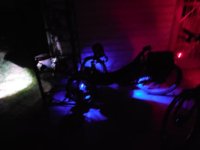
all my lights use less than 5w. I have four little soft blue lights shining on the wheels. car in interior stick on floor lights.
4.jpg

need a rear flashing red and add my other front head light.
 
All those pretty lights. But they will have to wait.

I need to get the basics done first.

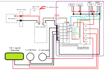
Had to plan in the wiring for the Stop-Turn- & Tail lights.

Here's my version, (in purple square) for perusal, and correction if needed.
fechter diagram - 2.png
 
That looks good. The turn signals need a flasher which would go between the fuse block and the turn signal switch. Here's one that I used on one of my bikes: https://www.ebay.com/itm/Two-Pin-LE...763899?hash=item3b25979e3b:g:VCoAAOSwXMxcG-dq I found it didn't work with LED lights unless I placed a 100 ohm resistor across the lights. This would not be needed with incandescent lights.

You will also want to tie the brake switch into the controllers when you get there. Check your controller instructions to see if they have a "high level" brake input. If there is only one brake input, I would assume it is the "low level" type, which needs to be switched to ground to activate. To do this, you would need a little relay or a transistor to supply a grounded signal when the brakes are applied.
 
Thanks fechter

I'm online as we post, looking at the many options for turn signal indicator switches, and lighting for various uses, i.e. ATV, motorcycles, golf carts, etc.

I'm trying to visualize the different choices, and how they might fit into my design.
I'm thinking of a 'dummy' center 'old school, gear shifter', that would hold the aforementioned switches. I have a dummy grenade, off from my PVC T bucket, that's destined for the top.

:idea: This dummy gear shifter, could actually be my parking brake.
Maybe it's not such a 'dumb' idea, after all....hmmmmm

I want to utilize the K.I.S.S method as much as possible.

Others ideas welcomed.
 
Just had a 'duh' moment.
I didn't wire in for the front turn signals.
 
I'm off to get my truck smog'ed, but wanted to throw this out there,
because I know it will be coming up down the line.

I've shown which connections, I don't think I will need, (or could be used for some other function).

Like I indicated in the drawing, I haven't taken the time yet, to see how they will connect up with the wiring/switches,etc, from the converter. Also, how if at all, I will be able to, or even want to, use the wiring harness, that came with the motors.Controller wiring 4.png
 
You'll have to do a little poking around with a meter to see how the two brake inputs work. I suspect the one labeled brake light is really a high level brake input, which would tie into the brake light wire.

No idea what the "indicator light" wire does.

The forward/reverse switch will have to go somewhere. It might be bad if it was accidentally switched when the motors are running.

The two-speed switch might need a jumper to keep it in high if you don't want to use a switch. Normally this feature limits the top speed to something lower when in low speed.
 
fechter said:
You'll have to do a little poking around with a meter to see how the two brake inputs work. I suspect the one labeled brake light is really a high level brake input, which would tie into the brake light wire.

No idea what the "indicator light" wire does. I think this is European for turn signal

The forward/reverse switch will have to go somewhere. It might be bad if it was accidentally switched when the motors are running. It's destined for the front of the console, near the other switches.

The two-speed switch might need a jumper to keep it in high if you don't want to use a switch. Normally this feature limits the top speed to something lower when in low speed. OK, I wasn't sure how to use it. The jumper idea, is planted, if needed thanks.

Do you think there's a possible use for any of the unused connections? Only thinking of future additions.
 
You're using most of them already. You'll need to sort out the brake wires with a meter but generally you use one or the other but not both. Not sure what the charge port wire is for. I'd guess it just goes to the main battery wires (another meter check).
 
My terminal blocks and switches are supposed to arrive tomorrow.

So I've spent most of my day working on updating, the wiring diagram.
My eyes are seeing double and triple. I have to stop here for a while.

It's getting more cluttered, but I think I've got it correct. I still wonder whether I should/need relays at any point. Maybe a larger fuze...40 vs 30 amp?
Anything else I'm forgetting, or don't know about ????

I'm hearing (seeing) a VROOOMMMM in the near future :D

StreetRunner wiring diagram.png
 
for my sb cruiser trike, i used relays on my lighting *only* because i use very thin wires up to the control switches on my handlebars, that can't handle the current needed for some of them (like the headlight).

so the control wires and small switches only need to handle a few dozen milliamps to turn the relays on, then the relays handle whatever is needed. i use cheap relays from amazon that have the 30a blade fuse built into them (or rather, the holder is built in and they come with a 30a blade fuse).


before i used the relays, i used direct wiring on all the low power stuff like the led strips, etc., but twice i have had wiring faults that then damaged the entire wiring run from overheating, requiring a complete rewire of the system to fix (because my control (throttle, ebrake, etc) wires also run in the same cable). if i'd used thicker wire that wouldn't have been a problem, but that many thicker wires wouldn't fit where i needed them to. hence, the thin wires, and now the relays. :)


so, in your case, you probably don't need the relays, just a fuse on the output wire from the 12v dc-dc unit (i'd put it as close to the dc-dc as possible, so that it will protect the dc-dc and the wiring from any shorts or overloads beyond the rating of the fuse.

the fuse needs to be just big enough to allow the maximum amps that all of your devices on the 12v system will use, if they all ran at the same time. but small enough that it doesn't exceed the max current that either the dc-dc or the wiring itself can handle.
 
Just_Ed said:
Anything else I'm forgetting, or don't know about ????

That looks great. 30A fuse should be plenty.

At some point you'll have to figure out the brake input to the controller, but that's sort of optional. It can run without that. I suspect you can just run the brake light signal to one of the inputs but worst case you may need a relay or double pole brake switch so you can ground the low level brake input when applying the brake.
 
It's Raining! ... It's Pouring! ... The Old Man is ...Drawing!

Thanks for the feedback.
Looks like all systems are 'GO' for hook up.

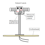
Just a little something I thought up last night.
During the course of designing and building,
I want to have many different points of interest so to speak.
Much rather in my mind, the interest is in the details.

Pedestal Controls.png
 
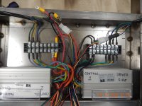
I installed two new terminal blocks, this morning.
These TB's are much better. The result is much cleaner,
with additional spaces for future needs.
A better picture later.

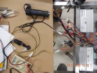
I wanted to start putting together some of the other components, for a power-on test. But quickly found that there is a disparity between wiring color coding. As you can see, there is a bunch of wiring, that closely resembles our LA freeways.

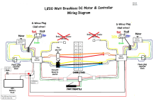
So I have abandoned the attempt, while I draw up an additional diagram, showing where the remaining controller wires go, and which colors they may change to, in their journey to their terminal block.

Cropped-wiring.png


Also, the wiring harness they gave me, really wasn't working for my use, while all bundled up.
So off came the wrapping and now they are all sorted out, each waiting for their assignments.

DSCN4363.jpg


I will use them as they are, w/connectors, or modify as needed.
I will reuse the wire wrapping, as necessary.

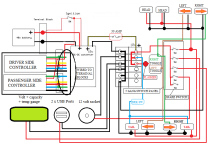
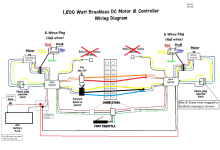
Below is a diagram of the remaining wire connections needed, before applying power to the motors.
It includes wiring for the key switch, the reverse switch and foot throttle.
I believe it is correct but haven't tried it yet. I would like some feedback first as to its correctness.

dual mtr diagram.png

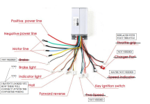
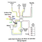
Suppliers diagram. Added for additional info.

mtr diagram.jpg
 
Looks OK.

I wouldn't assume the the motor and controller wire colors will match. They might or they might not. You pretty much have to do trial and error to test. You can get some pointers here: https://endless-sphere.com/forums/viewtopic.php?f=16&t=3484

You may want to figure out some way to temporarily connect the phase and hall wires to verify the wiring before making permanent connections.

Using the controller's reverse function may not be good for reversing the one motor as often the reverse mode is at very reduced power. You want both controllers to be in "forward mode" but swap the wiring around to make one go backwards.

One of the two wires for the ignition goes straight to the battery +. You can use the small wire supplied or you can wire directly to the main battery +.

The brake cutoff wires can be left disconnected for initial testing. Eventually you will need to sort out exactly what they do. Measure resistance from each of the wires to the main battery + and battery - and see if there are any direct connections.
 
It's raining, again...and on my parade as well.

I hooked up the connections for the switch and throttle, as per the diagram.
dual mtr diagram.png

I did leave out the forward/reverse switch..so maybe that is the problem.

Turned on the battery, turned on the switch, and nothing.

I checked for voltage to the terminal blocks, and that was OK.

DSCN4370.JPG

Switched from foot throttle to hand throttle.. still nothing.

DSCN4371.JPG

Tried continuity checking and all but the foot throttle had some sort of measurement.
That is if I did it correctly.

And there's this.

In this test, I'm turning the key switch to on and depressing the foot throttle. Nothing happens.

When I turn off the battery it lets out a loud screeching,(like dragging a metal table across the floor) and the display goes red, and the numbers drop.
At first, I thought I had (maybe I have/am) done something bad.
But it keeps doing it, each time I use it, so I'm wondering if it is just a characteristic of this type of battery.
https://www.youtube.com/watch?v=iq42rWLvgUU&feature=youtu.be
 
It should run with the brake and two speed switch wires disconnected. Not sure about the forward/reverse but most will run with that disconnected too.
There are several safety features that can prevent the motor from running.

First, I would check the throttle signal voltage. The main battery negative is the reference for signal voltages. The throttle signal should be a little below 1V at rest and go up to a little over 4V at full throttle. If this voltage is outside a certain range, it thinks the throttle has faulted and prevents operation. There should be 5v on the throttle power wire.

Also check each of the motor hall signal voltages. These should toggle between near zero and near 5v as you rotate the motor by hand (no throttle).

Check the voltage on the key wires.

If still no response, try separating the throttle wires to just run one motor.

I might need to review the supplied wiring diagram to see if there is a lockout or "anti thief" connection.
 
there's no sound in that video.

but the "screech" is likely a low voltage alarm.


btw, in the pic below, it looks kinda like you have the positive battery wire for one controller and the negative battery wire for the other still unconnected? if so, neither controller can work.

file.php
 
amberwolf said:
there's no sound in that video.

but the "screech" is likely a low voltage alarm.

btw, in the pic below, it looks kinda like you have the positive battery wire for one controller and the negative battery wire for the other still unconnected? if so, neither controller can work.

file.php

Yeah, I'm not sure why it didn't record the sound.

But what I'm confused about is, why it..listen closely...'Screeeeeeched' only when connected through to the motors.
The battery displays 57.1 volts, so I can't see why it would all of a sudden show low voltage. (when connected to a load)
I have sent an email to TechDirect, asking for their opinion. Maybe it's a characteristic of this type of battery.

The pos/neg wires you see are the leads that will eventually go to the converter.

I've been dealing with flood issues and clean up, so I haven't had the chance to do any of the checks fechter suggested.
Maybe today I'll get out there and have a look at it again.

I'm also thinking of just doing a direct 'touch and let go' approach from the battery to the motors, just to see if the motors actually work. Specifically bypassing the controller.
 
by Just_Ed » Mar 14 2020 9:20am
I'm also thinking of just doing a direct 'touch and let go' approach from the battery to the motors, just to see if the motors actually work. Specifically bypassing the controller.

Don't do that, the motor is not made for that, not a brushed DC motor.
 
ZeroEm said:
by Just_Ed » Mar 14 2020 9:20am
I'm also thinking of just doing a direct 'touch and let go' approach from the battery to the motors, just to see if the motors actually work. Specifically bypassing the controller.

Don't do that, the motor is not made for that, not a brushed DC motor.

OK, thanks for the prompt reply.
 
It's better to work thru the problem and don't get into a hurry. Building it is the best part, I built two before my trike, just to figure out all of it.
First one was a kit the plugged together, next was parts that was made to work together and then my trike that needed the wiring worked out like yours.
Took me three days just to wire the controller to the motor (can not sit to long) correctly. About three months total for my trike. Took my time and now 9 months and 2000 mi later still working good.

fechter and amberwolf are some of the best they will get you thru. I am enjoying reading about your build and look forward to when you finish but then it will be over. The next person can copy what you did and learn from your issues. That is what is great about this site!
 
ZeroEm said:
It's better to work thru the problem and don't get into a hurry. Building it is the best part, I built two before my trike, just to figure out all of it.
First one was a kit the plugged together, next was parts that was made to work together and then my trike that needed the wiring worked out like yours.
Took me three days just to wire the controller to the motor (can not sit to long) correctly. About three months total for my trike. Took my time and now 9 months and 2000 mi later still working good.

Thanks again ZeroEm

I am being careful, thus the reason for commenting on a direct connection. I was looking for feedback, and you provided it.

Thanks to the help I'm getting here, this project is the furthest I've gotten, on any of my projects. I have $$$ into these parts and because I know just enough to get in trouble, I have to be sure I know the (why), before I proceed much of the time.
 
Back
Top