Continuous Charge Amp vs Continuous Discharge Amp

Charged my 10S3P pack and with trickle charge until it maintained 41.05 volts (1:00pm yesterday). Checked it again six hours later at 7:00pm, and still 41.05 volts. Checked it this morning at 9:00am (20 elapsed hours) with self-discharge of 0.01V (20.04 volts). Will check it once a month for self-discharge from mid-November to mid-March, but not done etriking yet with Bluebird nest boxes that need cleaning, any repairs, relocate, etc. Still have 135 miles before reaching 2,000 miles of etriking since last August (and it was stored for 4 months over the winter).

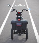
Did my third test run early this morning at a conservative pace. The first two test runs pulled an average of 8 to 10 amps until Controller cut-off. This third test run pulled my usual more conservative average of 4-5 amps until Controller cut-off. The photos are along the Luce Line State Trail (an old railroad bed most of the way) that I rode this morning to Wayzata for coffee and a blueberry bagel. The only steep incline was the bike lane bridge over highway (see photo). Used my own pedal power with a little motor assist in 3rd (pulled about 6-7 amps). If you guys ever come across a tombstone when you're a senior that reads, "Voltage Sag ... What's That ?" it may be my final resting place :wink:

Included a couple other photos taken along the Luce Line Trail (paved and gravel) this mornng. The guy at the bike station is changing the battery in his Pedal Power Watt Meter. On the way back i visited with another biker at that the same bike station. Still had 19 miles to go before reaching his destination. Asked him what he thought of a bike Power Meter and he said, "It wouldn't be of much use to me, i'm 77", but he sure didn't look it.

The other photo of the 4 cross country high school gals was early this morning on my way when it was only 57 degrees. Me ... wearing a sweater, light jacket and stocking cap. Minnesota girls are a hardy breed (probably hockey gals). Received four nice compliments on my etrike this morning. The gal at Caribou having seen me pull up out of her window said, "I need to get one" (and she meant it). Then a toddler being pushed in a stroller my his mom said, "cool" and another person said, "That is so neat!". And the fourth comment from a senior citizen when i was coming back at a faster clip (after changing to unitpackpower battery), "Look at that go!"

This time i changed to my backup unitpackpower battery after the first Controller cut-off at 32.25 volts. To my surprise the P-group variance (after checking once home) was higher at 53mV with just the first cut-off; whereas, my two previous test runs were lower (45mV and 41mV) after three and then two successive cut-offs which should have caused even more imbalance than stopping after the first Controller cut-off. The 53mV variance of my 10S3P was measured one hour after the Controller cut-off coming back while still on the Luce Line Trail.

Balance charging began after 1 1/2 hours rest from Controller cut-off. Bottom balance charging the two paralleled 5S3P packs at .5C (1.5 amps). After 10 minutes the ten P-group variance was down to 39mV, after 20 minutes 22mV, after 30 minutes 11mV. Then stopped to post this. Will conclude with some more data and summary of my balance charging Vruzend 10S3P 30Q 141 experimenting tomorrow and/or following day.

Hope you all are having a relaxing Labor Day :thumb:
 
goatman said:
if you bottom balance the pack at 3.0v then just charge to about 4.15v.

i discharge my packs to 3.0v/group under full volt sag but really i discharge to about 3.2v

Yes, bottom balance to the voltage just below what you usually use as your "drop dead never below" LVC

Of course you get **much** better cycle lifespan by stopping earlier, but this is a good strategy for worn / unbalanced cells if you do need to pull them down so low.
 
IMO, bottom (and middle) balancing is a waste of time and effort. Sure it'll work, BUT, what do you think is the benefit over top balancing ?

Bottom balancing is a PITA, since you have to wastefully (wasteful in time and cycle life) discharge all cells to a set low voltage, then wait for the outliers to catch "down" to the rest, then recharge. Worst. Idea. Ever.

Middle balancing, since it's in the flattest part of the discharge curve, means you get the largest range of SOC between each cell for a given balance voltage tolerance. Second. Worst. Idea. Ever.

Top balancing is straight forward and quick(er), and since a pack will often be fully charged anyway, it is the ideal place to balance, as it just follows on at the end of the charge cycle. In addition, top charging is the de-facto standard, so most equipment is designed to function that way.
 
serious_sam said:
IMO, bottom (and middle) balancing is a waste of time and effort. Sure it'll work, BUT, what do you think is the benefit over top balancing ?

That's what i too used to believe, but found out over 150 charge/discharge cycles that it makes more sense to first bottom balance than middle or top for my use (cycle life longevity). That said, if you prefer to top balance then by all means do what you think is best for your battery pack :) As for me and my pack it's balance charging all the way. Being retired i don't need to do a fast bulk charge anymore (been there done that). Your needs may be different than mine so do what you think works best for you :)

As for me have to agree with spinningmagnets that if you were only going to do just one of the three (bottom, middle, top) bottom balancing makes the most sense for the majority of the time. Are you aware that it takes considerably longer to top balance a pack (ACAP) than bottom balancing. Each has it's own purpose depending on an ebiker's unique needs :thumb:

Here's just a little of my background from a teenager up to and including retiring ...

  • Rebuilt a Whizzer motor bike and engine including grinding and seating its two valves when a teenager. The bike was $5 and the motor for $5 in a junk yard in a box disassembled. It needed a new crank ($25 ouch) and was missing the screw-in dip stick. Before that project i had built a motor bike using an older Briggs & Stratton with centrifugal clutch.


  • One of 30 in the nation chosen to attend an 8-week Instructional Technology Seminar at the University of Southern California with two top IT instructors from USC and Ohio State. Government grant money including room and food stipend.

  • Maintained a 3.85 GPA for my MS degree, while holding down 2-3 part-time jobs.

  • Designed and custom built an intercom system (during summer break) in a middle school with 23 classrooms including running installing conduit above the ceiling panels, pulling all the wiring, using a jack hammer to run some of the wires through a tunnel, custom built the control console and installing it in the school office.

  • Chosen as an Outstanding Young Educator in 1971-72 school year as District Audio-Visual Director.

  • Quality Control Technician for Medtronic helping the Engineers solve technical and mechanical problems before the product was approved for assembly line production.

  • Rebuilt 1989 Honda engine (been to U-pull R parts many times). Body work on my 1970 Thunderbird and spray painting. Buying new repair parts from RockAuto for my 2011 Nissan Versa SL hatchback.
_________________

Here's one of my EABL (Eastern Bluebird) nest box designs similar to the popular Gilbertson nest box. Split the PVC then spread it to fit into the front groves (provides a little more room so the nestlings aren't so cramped before fledging. The PVC wants to return to its original shape so its pressure is enough to keep it secure in the grooves of the cedar front entrance. The roof is attached to the conduit support column. That way the nest box can be easily removed (if you know how) for monitoring and cleaning just like the Gilbertson nest box. At one time Dick Peterson's nest box design was the most popular design across America for years. The newer Gilbertson design offers some advantages over the Peterson. And the EABL's aren't complaining as they find it inviting.
 
serious_sam said:
Top balancing is straight forward and quick(er), and since a pack will often be fully charged anyway, it is the ideal place to balance, as it just follows on at the end of the charge cycle. In addition, top charging is the de-facto standard, so most equipment is designed to function that way.
It stands to reason (makes sense) that if the P-groups variance is 45-50mV after Controller cut-off to first bottom balance charge for say 30 minutes (depending on how out of balance) at .5C before doing a straight bulk charge at 1C or a Fast Charge. It's also understandable that to balance charge a 10S or 12S pack with a 2S to 6S balance charger you need to split the pack for balance charging. Thus serious-sam makes a valid point as it's too much bother (unless you're retired) ... even if it's a neat idea for treating your pack with TLC and hopefully prolonging its cycle life.

Decided to do another test run at full throttle this afternoon. My most rigorous test run to date and up inclines this time without pedaling. Only 1 bar still showing when I got to Davanni's to take a break for some Lasagna before heading home. Will bottom balance for 30 minutes at .5C, straight charge at .5C and then use my technique to top balance the ten P-groups within 5mV in a few minutes. My top balancing technique (when not using a 2S-6S balance charger) takes only a few minutes.

Will explain tomorrow and post results showing that bottom balancing makes sense before straight bulk charging at 1C, if that's your preference instead of .5C.
serious_sam said:
IMO, bottom (and middle) balancing is a waste of time and effort. Sure it'll work, BUT, what do you think is the benefit over top balancing ?
Au Contraire (IMO) ... the test results tomorrow will hopefully prove a point that bottom balancing makes sense.

One reason why many think top balancing is the way to go is because of majority of BMS' don't balance charge until the very top. Thus, top balancing must be the best choice (yes and no). Depending on how out-of-balance the pack is it could takes hours to top balance and then only within 25 mV. That in itself is reason enough to first bottom balance at the same time you are balance charging the pack. It's not wasted time, but wise time :thumb:
 
goatman said:
last comment on the subject :D battery murder system correct :thumb:

id just like something as described like a cell balancer with bluetooth and an on/off switch independent of the pos/neg battery leads that way i can turn it on, look at the voltages and if alls fine then turn it off.
Why not add another set of balance leads to same contact P-group BMS leads and plug in a cell logger to the balance lead connector? You could have it mounted on frame where it's always handy. May have to get a balance lead extension.

Those knock-off $60 Chinese balance chargers aren't all that accurate. My 150W Duo (2S-6S) may be sufficient for the needs of most RC Lipo flyers, but it didn't take long for me to realize it was inadequate for my experimental balance charging tests. The individual cell voltage readouts were way off. Possibly a combination of cheap components and assemblers not taking the time to balance the individual cell voltage readouts.

Soon discovered that my old 70W Balance Charger was by far more accurate with more readout information. Without a good mulimeter you still don't know how balanced the cells are without taking voltage readings from each of the 5S balance lead connector contact points. Any difference between my older Balance Charger cell voltage readouts and my multimeter voltage readouts were only a difference of about 5mV with the multimeter voltage readings of course being more accurate.

After balance charging over the past months cell #1 has always been 0.01V lower than cells #2-4 and cell #5 always highest by 0.01V (i.e. 4.11, 4.12, 4.12, 4.12, 4.13). Then for the heck of it having nothing better to do i made my own top balance discharger using 2-12V headlight bulbs, piece of wood and probes to discharge cells 2-5 and then cell 5 until all read 4.11V. This took no longer than 5 minutes as a practical top balance experimental solution. The vast majority of BMS' only balances the P-groups within 25mV of each other. Basically the same principle as those little RC blinkety blink top end 2S-6S Lipo balancers that are s-l-o-w and s--l--o--w--e--r.

The bottomline is that bottom balancing is the preferred choice if your only option is; Bottom, Middle or Top as you'll soon see. Here's some data from yesterday's test run based not only on goatman's preference, but all ebikers that the cells are designed to be discharged at 3C and higher. This test run yesterday was at full throttle 90% of the time going up some inclines with very little pedaling (4C-5C) until the Controller cut off at 32.25 volts. Because the total weight including the etrike is 240 pounds the accumulated mileage at cut off was 7.2 miles (750W rated motor) with my DIY 10S3P 30Q 141 pack charged to 4.1V and discharged to 3.25V.

  • Resting voltage after one hour was 42mV imbalance between the ten P-groups.

  • Balance charged at 1.5 amps (.5C) for 30 minutes with 4-5mV of imbalance.
    4.5mV has always been the lowest imbalance at 30 minutes with the imbalance then increasing whether balance charging or straight bulk charging to 12mV imbalance.

  • In previous post had said i would change to bulk charge at 1C to 4.10V after first 30 minutes, but instead decided to bulk charged at 2.8 amps to prove that bottom balancing makes the most sense if your only choices were: bottom, middle or top.

  • After balance charging at 1.5 amps for 30 minutes changed to straight bulk charging at 2.8 amps.

  • At 19.94V (two 5S3P packs) 12mV imbalance.
    At 20.34V (two 5S3P packs) 14mV imbalance.
    At 20.57V (two 5S3P packs) 15mV imbalance.

  • At 20.62V reversed course with 9-10mV imbalance. In order to establish a resting voltage of 20.50V charge to higher voltage (20.62V). Resting voltage after 1 hour: Cell 1- 4.10v, cells 2 thru 4- 4.11V, cell 5- 4.12V.

  • After the first 30 minutes at 1.5 amps (.5C) of balance charging (17.35V - two 5S3P packs) the imbalance was the lowest at 4-5mV (this has always been the case). Then with bulk charging at 2.8 amps the mV imbalance increased from 12 to 15mV (balance charger voltage readings) until for some unexplainable reason decreased to 9-10mV at the top end from cells 1 through 5 from 4.10V to 4.12V (multimeter voltage readings).

  • Typical example of the difference between even a better balance charger as opposed to a $60 inferior balance charger with unreliable voltage readouts vs my multimeter showing a voltage imbalance of 20mV (4.10V - 4.12V). Even my older $85 Taiwan balance charger and most all balance charger voltage readouts aren't as accurate as the voltage readouts from a good multimeter. My $60 Chinese balance charger at least provides IR cell readouts, but even they aren't accurate. They will give you a general indication of increasing IR of P-groups as the pack ages and whether or not one or more P-groups are having a problem.
______________

The two 5S3S packs have always read the same identical P-group multimeter voltages during charging even after resting for an hour (i.e. 4.10V, 4.11V, 4.11V, 4.11V, 4.12V)
When i decided on my Vruzend DIY build using the newer 30Q 141 cells i never intended to use a BMS from the Get-Go. This is not to say you shouldn't, but i didn't want to incorporate a BMS for the purposes of my experimental project to track any significant self-discharge and number of charge/discharge cycles before reaching 60% of rated capacity.
 

Attachments

  • The Fast Lane.jpg
    The Fast Lane.jpg
    119.3 KB · Views: 231
The reason the top end voltages (20mV variance) between the P-groups with Cell #1 at 4.10V, Cells 2-4 4.11V and cell #5 at 4.12V (the two 5S3P split packs) is again because that's the closest accuracy of my balance charger and possibly even more expensive balance chargers. In other words it's close enough when you consider most BMS' only top balance within 20-30mV. So, the top end voltage variance had nothing to do with wiring, bus bars or it being a Vruzend V2.1 Kit.

Decided to do one more test run later this morning and use my old 6S Blinky Balancer for bottom balancing. Then straight charge at 2.8 amps (1C) from 17V to resting voltage of 20.5V (split 10S3P pack). Then also top balance with Blinky balancer and report back with results later today.

The reason Blinky cell #1 never lite up even once during my lengthy two hour preliminary top balance test yesterday could be because Cell #1 was the lowest at 4.10V with the other cells from 4.11V to 4.12V OR Cell #1 red light is burned out or defective Blinky. That's why some refer to them as a "Blinkety Blink" discharge balancer because for one reason they are slow going, but for RC use they're handy to carry around in your pocket or sit on a shelf as just another little gadget ...
 
Again (and again) as far as the impact on the cells themselves go, the SoC% where you choose to balance in itself makes **no** difference.

Except that the choice enables your HVC or LVC triggers to be based on pack level voltage rather than needing a BMS for cell-level monitoring.

Also again, top balancing is fine, so long as (assuming you care about maximising longevity) you have the gear to do it within parameters that do not shorten lifespan. That means adjustable start-balance voltage and a fast enough balance current so you are not significantly extending the time spent near Full SoC.

Unfortunately most cheaper BMS have a single hard-coded start-balance voltage and a very low balance current. THAT norm is what causes problems with top balancing.

Now, if your cells are new and well matched, thus balancing is only needed once every few months

or you do it every cycle and the added time is just 5-10min

then for the first part of their lifespan, no worries!

If however as the pack ages longer balancing times or higher frequencies are required, best to change the tool and/or the strategy you use, but agai,, only if you care about maximising longevity.

eMark said:
if you were only going to do just one of the three (bottom, middle, top) bottom balancing makes the most sense for the majority of the time.
And again, this implies one could choose to do bottom balancing "first" and then later balance at a different SoC/voltage.

That is impossible. And trying to do so a complete waste of time, only the last one counts, wipes out anything accomplished at the other SoC/voltages.

Your not grokking that fact, shows zero understanding of the reason for balancing, how the concept itself works.

_______
> Are you aware that it takes considerably longer to top balance a pack (ACAP) than bottom balancing?

Also completely false. The time required has **nothing** to do with the SoC/voltage level chosen.

It completely depends on which of the three balancing methods used - not top vs bottom, but active vs passive, resistive vs capacitive for example

and **most** importantly, the balancing current rate allowed by the specific gear used.
 
i like to read Johns posts with the voice of "Foghorn Leghorn" in my head " again, again I say" try it, itll make you laugh :D

the topic of : length of time spent up top, top balancing with a current being pushed in

while doing my cycle tests i can only go to 0.10amp cut off for the charge to 4.2v and the few batteries ive tested dont stay at 4.2v, theyll drop to 4.191v or 4.185v once the charge has completed. so why charge to a top balance and not just bleed down with a bottom balance blinky blink then charge to a top pack voltage and leave them out of balance at the top?
 
goatman said:
while doing my cycle tests i can only go to 0.10amp cut off for the charge to 4.2v and the few batteries ive tested dont stay at 4.2v, theyll drop to 4.191v or 4.185v once the charge has completed.
It's normal as i charge my two paralleled 5S3P packs to 20.62V to maintain a resting voltage of 20.50V (or 41.0V for 10S3P pack).
goatman said:
so why charge to a top balance and not just bleed down with a bottom balance blinky blink then charge to a top pack voltage and leave them out of balance at the top?
Hopefully, the discharge test run this morning and following charge will help.

  • Controller cut off (32.25) with imbalance of 50mV (lowest P-group 3.35V, highest P-group 3.40) after 30 minutes. P-group #1 3.35V, P-group #2 3.39V, P-group #3 3.40V, P-group #4 3.36V, P-group # 5 3.39V. After 1 hour the imbalance was 40 mV which i considered the resting voltage with P-group #1 3.37V and P-group #3 the highest at 3.41V. Also take voltage readings of P-group #1-#3 = 10.18V, P-group #2-#3 = 10.19V, P-group #3-#5 = 10.20V for an imbalance of 20mV which may be more representative of bottom imbalance.

  • Then remembered that the Astro Blinky doesn't discharge balance until cells are at 3.70V to 3.80V. So, I did what most of us do and bulk charged the two paralleled 5S3P packs to 20.62V to achieve a resting voltage of 20.50 volts (41.0V for 10S3P).

  • The P-group voltage imbalances 13-14mV at 17.50V, 17-18mV at 18.00V, 18-19mV at 19.00V, 20-21mV at 20.00V and 23mV at 20.62V with P-group #1 the lowest at 4.102V and P-group #5 the highest at 4.125V (23mV imbalance). This has always been true with the problem with the balance charger voltage inaccuracy as even a BMS can only balance within 20-30mV.

  • Then using the Astro Blinky discharge balancer to equalize the P-groups to 4.10V which took two hours. But is that even necessary to prolong cycle life longevity in that a BMS only balances within 20mV ti 30mV ??????

The photos are pretty representative of the Blinky with cells 3-5 blinking the most, then cells 3-5 and cells 4-5. Cell #1 never blinked. I thought maybe that Blinky was defective, but when you first plug it in to the 5S balance lead connector all the red LEDs light up for a couple seconds to let you know they all are working ...
 

Attachments

  • Cells 4-5 Discharge Balancing.jpg
    Cells 4-5 Discharge Balancing.jpg
    102.1 KB · Views: 190
goatman said:
while doing my cycle tests i can only go to 0.10amp cut off for the charge to 4.2v and the few batteries ive tested dont stay at 4.2v, theyll drop to 4.191v or 4.185v once the charge has completed
Probably normal whether Lipo or LiIo. Just as there is some voltage bounce up after discharge cut off ... there is bounce down after charging cut off. Have to charge my two paralleled 5S3P packs to 20.62V, so that the resting voltage of my 10S3P pack is 41.1V. Then with Blinky balancer discharge all P-groups to 4.10 volts.
goatman said:
... so why charge to a top balance and not just bleed down with a bottom balance blinky blink then charge to a top pack voltage and leave them out of balance at the top?
I've never charged my 10S3P to 42.0 volts as my objective is prolonging cycle life longevity ALAP. Charge my paralleled 5S3P packs to 20.62V to achieve resting P-group voltages after 30 minutes of around 4.10, 4.11, 4.11, 4.11, 4.12). Then Blinky discharged all P-groups to 4.10V, but that's too time consuming for the needs of ebikers and probably not necessary as explained in next paragraph. This experimental Vruzend split 10S3P pack was done for my own conservative etriking and experimenting along the way (not practical for the majority of ebikers).

What i've come to believe over the years with Lipos and finding out again with my 18650 cycle tests is that it doesn't make a lot of difference whether bottom balancing, middle balancing or top balancing. These cells (whether Lipo or LiIo) develop a memory of how they've been treated as to any standard or dis-standard of treatment --- whether arbitrary TLC :wink: or arbitrary abuse :wink: . The key, if there is one, is how to best discharge the cells while keeping the P-groups as balanced as possible (minimal mV imbalance) along the journey. Apparently Elon Musk knows how best to achieve this with his Tesla battery. Me thinks there is an advantage to having thousands of cells working together to keep each other balanced (minimal imbalance ALAP) during discharge and recharging before cut off.

My next test runs will be to establish the best discharge cut off (3.3V, 3.4V, 3.5V, 3.6V) for my etriking needs so as to prolong cycle life ALAP. Will next attach my two cell loggers to each 5S3P balance lead of my 10S3P pack and set the alarms to 3.6V and record results using different charging from bottom balancing to top balancing and no balancing (bulk charge) to see what the P-groups imbalance is after a one hour rest at 3.6V cut off. My guess at this point so far is that no matter what balancing method or just bulk charging the ten P-groups may be so similar after 3.6V discharge to draw any conclusions. Will charge at .5C (1.5 amps) as the suggested 18650 industry "Standard Charge" among the majority of 18650 cells ... https://secondlifestorage.com/celldatabase.php

The cells (Series strings and Parallel groups) in our DIY battery packs are going to do what they want to do (IMO so far) in spite of whether they are bottom balanced, middle balanced or top balanced. My Vruzend experimental 10S3P has given me the opportunity to learn all the area trails, meet interesting people, enjoy the sunshine and fresh air, get pedaling exercise, further by interest in bluebirding and do some experimenting FWIW.

goatman said:
... then charge to a top pack voltage and leave them out of balance at the top?
Serious_Sam was just as right in his belief that top balancing is the preferred method. Apparently it doesn't make a whole lot of difference whether first bottom balancing the P-groups or top balancing as the imbalance after discharge cut off at 32.25V among the ten P-groups is about the same (32mV to 41mV) after one hour rest. The unresolved question is how much imbalance at the top is too much imbalance after charging. Apparently more than 30mV is too much according to the industry standard of most BMS manufacturers. So far the most imbalance (my 10S3P pack) at top end whether bottom balance charging, all balance charging or just bulk charging whether .5C or 1C is 23mV of imbalance between the ten P-groups ranging from 21mV to 23mV.
 
Back
Top