
mr.electric
10 kW
message Green Machine he has the frame I bought.teklektik said:Pretty neat frame. I can't seem to locate a site for them - you you have a link or are they local only?mr.electric said:I bought the frame from Extreme Green.
message Green Machine he has the frame I bought.teklektik said:Pretty neat frame. I can't seem to locate a site for them - you you have a link or are they local only?mr.electric said:I bought the frame from Extreme Green.
mr.electric said:I wonder if the pedals will unscrew themselves being flopped to the opposite side? I could just tighten the hell out of them and call it a day.
[/quote]I will probably run a derailleur in the back and a 9 speed with a rapid fire type lever.[
")
mr.electric said:I can buy a "double freewheel " but I will test the bike with the jack shaft configuration first. The cranks will be switched but that should be ok. I wonder if the pedals will unscrew themselves being flopped to the opposite side? I could just tighten the hell out of them and call it a day.
What's the power rating of that fry pan?spinningmagnets said:edit: here's a pic from July 2010 with a 10-inch diameter pan to show how it was possible:
 Getting closer to test drive time. Is there a chance this motor will turn too slow ? You do all this struggle for no benefit in hill climbing at all
I am just running a single for the first test drive. I need to order a few parts to be able to set up gears. The motor sprocket has teeth for a bmx chain, the rear sprocket must match otherwise the chain is a mix match and will not mesh. I will need to use a sprocket removed from a cassette or a front chain ring on the motor to allow use of a 7sp chain and then I can switch the back to a 7sp freewheel and add the derailer. First I want to test drive to get an idea of what size sprocket I will want to run on the motor shaft.crossbreak said:No, you start from 5:1 and get to 6:1 after conversion. Again, what battery voltage and turn count will you use?
I see you do single speed. That's a decline of this conversions purpose
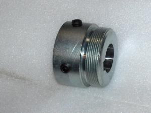
spinningmagnets said:The jackshaft configuration of a converted motor will only need a single freewheel on the left side (which is originally the right side of the motor), so without a gear cassette, a rear axle will now have its fat part on the left (with the stock threaded gear-mount removed).
What is the diameter and exposed length of the MAC and Bafang shaft (the part which is normally under the stock gears)?
thanks Bob for measuring I was about to check for spinning magnets.spinningmagnets said:The jackshaft configuration of a converted motor will only need a single freewheel on the left side (which is originally the right side of the motor), so without a gear cassette, a rear axle will now have its fat part on the left (with the stock threaded gear-mount removed).
What is the diameter and exposed length of the MAC and Bafang shaft (the part which is normally under the stock gears)?
#40 chain is the same pitch and roller diameter as bicycle chain but the width (and therefore the sprocket thickness) is greater. See here for dimensions: http://www.gizmology.net/sprockets. #40 sprockets are available down to 8t with boss and pilot bore


mr.electric said:I'm having trouble with the motor pulling so hard that it swings forward bending...
mr.electric said:Regarding bmc weird timing. Does this apply to Mac puma and others geared motors or just bmc?
I am looking forward to trying the ku 123 controllers on other motors. After replacing hall sensors I realize how much I like sensorless options.
mr.electric said:I'm having trouble with the motor pulling so hard that it swings forward bending the area of the frame the bracket bolts to. I will probably add another anchor point to the bracket and add an axle puller type chain tensioner to the rear wheel and see how it goes. I think a larger motor sprocket will help too. I would like to make an adapter that allows me to run a small crank chain ring on the motor shaft. I'm not sure if I should start with an old crank or start from scratch on this type of adapter hub. I think it should be nice and wide covering a good two inches of axle to avoid axial run out.