
The linear force, pulling the axle and motor shaft toward each other, can be minimized by using bigger sprockets, as described earlier.
You are using an out of date browser. It may not display this or other websites correctly.
You should upgrade or use an alternative browser.
You should upgrade or use an alternative browser.
Converting a hubmotor to a middrivemotor
- Thread starter crossbreak
- Start date
Perhaps a quick fix is to bolt up an adjustable rod between the dropout and the motor mount similar to a auto tie rod or as shown here in a disk brake adapter. The rod would run along or slightly above the centerline of the axle and motor shaft - the right side motor mount would need to be re-fabbed with a mounting ear. Threaded rod ends are available from Grainger and elsewhere for cheap. Painted to match it wouldn't be too noticable or at worst would have a similar military utilitarian look.crossbreak said:The best soltution is a bar connecting both chain sprocket axles.mr.electric said:I'm having trouble with the motor pulling so hard that it swings forward bending...
Anyhow, a pretty quick and easy fab...

mr.electric
10 kW
I took a test drive and was pleased with the acceleration and top speed. I think the small motor sprocket will be good for normal riding if I can tame the torque. I may pass the frame stiffening job to the machinist who made the motor bracket since I have other issues to tackle.
After a few blocks a grinding noise developed. I backed the bike up ( turned the wheel backwards)and the noise disappeared only to return after another half block of riding. Then the controller cut out at top speed for some unknown reason. Upon returning I found the motor shaft did not want to freewheel in reverse until I turned it briskly with a crescent wrench on the shaft, then the freewheeling returned and grinding noise disappeared. I will open the motor soon to inspect. I suspect something like the planetary carrier or rotor is now free to walk along the shaft and scrub on something else. In any case the block I rode with the grinding noise will have left some tell tale marks to show where there is interference. I also guess the controller was intermittently shorting or shutting due to over current due to the binding.
I only hope the windings were not damaged as the other parts of the motor are more easily repaired.
MitchJi
10 MW
Hi,
You are planning to run a chain from the right side of the cranks to the motor? If so a fixed sprocket on the freewheeling motor shaft (prevents back-pedaling the motor when pedaling with the motor off) to the rear plus a freewheel on the motor shaft to the cranks (prevents the motor from back-driving the cranks) will work well.
One advantage over crossbreak's configuration is you could easily use a something like a Schlumpf Two Speed Crankset or a double chainring to change your pedaling ratio independent of the motor-rear-wheel gearing. The problem for most of us is that without a custom frame it's hard to mount the motor between the crank and rear wheel. What I really like about crossbreak's left-side crank drive configuration is that he has figured out a way to get a most of the benefits of that configuration (no freewheeling cranks required, not necessary to gear the motor all the way down to crank rpm).
crossbreak
1 MW
mr electric, I spend some time to make the axle rotate really free without friction, had to grind off some material and insert some shims between rotor and stator carrier as well as to the planet carrier. I ordered a bunch of shims with 0.1mm, 0.2mm and 0.5mm thickness and 12mm, 15mm and 17mm inner dia before I started the bafang conversion, can't tell what I used in the end, just added shims till it was a good fit and the axle still rotated freely. Plz report on this, where exactly shims are needed.
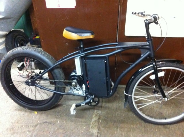
BTW having the motor in front of the BB rather than in the frame triangle made mount flexing almost disappear at all (since the straight line to the wheel), I use tiny 1.5mm steel sheets as a mount to the BB.
MitchJi, thx for the flowers") the left side crank idea was mostly born from the knowledge that one does not need a large spread when going for more than a kilowatt. What we need is a large "virtual" front sprocket, having 70T or so. 200% spread is enough IMO, using 16T-34T sprockets on the wheel. Even a steep hill can be climbed with 20kph if one has a kilowatt motor. found this comparison on a 13% grade hill between fixed ratio and and shifter setup, this is off any scientific reproducibility, but i think it show in which direction this aims: http://www.youtube.com/watch?v=0_QTfPl4rKw&feature=player_embedded
the left side crank idea was mostly born from the knowledge that one does not need a large spread when going for more than a kilowatt. What we need is a large "virtual" front sprocket, having 70T or so. 200% spread is enough IMO, using 16T-34T sprockets on the wheel. Even a steep hill can be climbed with 20kph if one has a kilowatt motor. found this comparison on a 13% grade hill between fixed ratio and and shifter setup, this is off any scientific reproducibility, but i think it show in which direction this aims: http://www.youtube.com/watch?v=0_QTfPl4rKw&feature=player_embedded
The more power/weight you have, and the less top speed you wanna gain, the less spread you need.
My next setup will have 6kw and will only do 40mph (it could do 60mph). This way it can be single speed and will be able to climb 50% gain hills. At 40mph, it will face more than 2kw drive load and though be still efficient.
Also, using a left side crank makes it possible to implement a pedal torque sensor throttle mode without the need of an expensive (130euro) magnetostriction torque sensor, one can simply measure pedal torque with a strain gauge build into the mount. This is not possible if the pedal chain is on the right, since then it is not possible to separate mount flex induced by the motor from flex induced by the pedals.
BTW having the motor in front of the BB rather than in the frame triangle made mount flexing almost disappear at all (since the straight line to the wheel), I use tiny 1.5mm steel sheets as a mount to the BB.
MitchJi, thx for the flowers
the left side crank idea was mostly born from the knowledge that one does not need a large spread when going for more than a kilowatt. What we need is a large "virtual" front sprocket, having 70T or so. 200% spread is enough IMO, using 16T-34T sprockets on the wheel. Even a steep hill can be climbed with 20kph if one has a kilowatt motor. found this comparison on a 13% grade hill between fixed ratio and and shifter setup, this is off any scientific reproducibility, but i think it show in which direction this aims: http://www.youtube.com/watch?v=0_QTfPl4rKw&feature=player_embeddedThe more power/weight you have, and the less top speed you wanna gain, the less spread you need.
My next setup will have 6kw and will only do 40mph (it could do 60mph). This way it can be single speed and will be able to climb 50% gain hills. At 40mph, it will face more than 2kw drive load and though be still efficient.
Also, using a left side crank makes it possible to implement a pedal torque sensor throttle mode without the need of an expensive (130euro) magnetostriction torque sensor, one can simply measure pedal torque with a strain gauge build into the mount. This is not possible if the pedal chain is on the right, since then it is not possible to separate mount flex induced by the motor from flex induced by the pedals.
bØb
1 W
mr.electric said:I took a test drive and was pleased with the acceleration and top speed. I think the small motor sprocket will be good for normal riding if I can tame the torque. I may pass the frame stiffening job to the machinist who made the motor bracket since I have other issues to tackle.
After a few blocks a grinding noise developed. I backed the bike up ( turned the wheel backwards)and the noise disappeared only to return after another half block of riding. Then the controller cut out at top speed for some unknown reason. Upon returning I found the motor shaft did not want to freewheel in reverse until I turned it briskly with a crescent wrench on the shaft, then the freewheeling returned and grinding noise disappeared. I will open the motor soon to inspect. I suspect something like the planetary carrier or rotor is now free to walk along the shaft and scrub on something else. In any case the block I rode with the grinding noise will have left some tell tale marks to show where there is interference. I also guess the controller was intermittently shorting or shutting due to over current due to the binding.
I only hope the windings were not damaged as the other parts of the motor are more easily repaired.
I suspect you may have found the torque limit of the clutch on the planet gear carrier
Another possible failure can be the bearings in the planet gears or the pins they ride on. Both are subject to some very high radial loads. Your motor sprocket really needs to be bigger to reduce the chain pull along with a compression strut between the right drop out and motor. Unfortunately this is also going to increase the distance between the chain and the chain stay. Better yet would be to lower the motor between the chain stays. Of course that would mean frame mods :x If motor torque was the primary bending moment here, how does a front fork ever survive a geared hub motor? I'm not talking about twisting out loose drop outs. You are only producing 17% more torque than the same hub motor at the same power and you are not producing appreciable bending moment in the chain stays by the wheel trying to push the bike forward. Unlike the stress on the front fork at the frame head when the front wheel is trying to pull the bike ahead.
Motorcycles only stared getting "thick" swing arms when they got horizontally mounted rear shocks. The "laid down" shocks needed a longer moment arm to work like a bell crank to move the rear wheel vertically. Motorcycles control swing arm bending moments and suspension squat by keeping the chain as close to the top of the swing arm as possible. Even letting the chain rub the top of the swing arm when the rear suspension is unloaded. You will also notice that some suspension mountain bikes they actually raise the swing arm pivot above pedal crank center to reduce squat with higher torque. Getting the chain line lower is going to become more important with more power.
I try to think of gearing as trying to keep the motor in it's sweet spot for economy at the load present. More performance is only gained with more power or less weight
Diesel Electric Locomotives only have one gear ratio for the electric motor to the wheel
bØb
crossbreak
1 MW
he did 1250W power limit, but no one knows the phase current limit he uses. It's hard to make a remote diagnosis from that. A 1:1 battery->phase current would solve this easily if too much torque is the issue. If the rotor was blocked this should have left obvious legacy.
mr.electric
10 kW
I will open the motor and take pics after work today. I feel that adding a spacer like crossbreak mentions should solve the grinding. Normally the axle is fixed into the hub because the stator is sandwiched and has no axial play. Now that the axle is free it has endplay and could probably cause the rotor to contact something else in the motor. That is my theory anyways. I may need to add a c clip some where too. I have had good luck cutting c clip grooves in motor shafts by spinning the axle and touching a hack saw blade to the spinning axle.
Ebike building is such an awesome hobby! I really enjoy the discovery part of it.
Ebike building is such an awesome hobby! I really enjoy the discovery part of it.
bØb
1 W
mr.electric said:I will open the motor and take pics after work today. I feel that adding a spacer like crossbreak mentions should solve the grinding. Normally the axle is fixed into the hub because the stator is sandwiched and has no axial play. Now that the axle is free it has endplay and could probably cause the rotor to contact something else in the motor. That is my theory anyways. I may need to add a c clip some where too. I have had good luck cutting c clip grooves in motor shafts by spinning the axle and touching a hack saw blade to the spinning axle.
Ebike building is such an awesome hobby! I really enjoy the discovery part of it.
I have in past years I have cut quite a few snap ring grooves. There are much better ways to cut a groove than to touch a hacksaw to it while it is turning. It is almost guaranteed that the groove won't end up where you wanted it. The exception to this is to put a shaft collar around the shaft and cut against the side of the collar, but you have to have collars for every size shaft. You can make a quick v block to use with a variety of shaft sizes from a piece of steel angle iron. 1/8" thick is fine, but leg lengths need to be 3 or more times the size of the shaft you are working with. The length is not special, but if you cut it the length of the shaft you are using it will work real nice. About 1/3 of the length from one end tack weld a piece of 1/4" ~ 3/8" key stock that is about a 1/2" longer than the width of your vise jaws to the root of the angle on the outside. You do have a vise? Mama couldn't have put a meal on the table at our house without a good vice
Don't get real wild with the welding or you will warp the angle. Just a good fat tack on each end will work fine. That way you won't warp it and the weld won't get in the way of the vise jaws. The key is just to hold the jig in the vise. Over about the middle of the key lay a square butt scale (combination square for carpenters across the ends of the angle legs. ACCURATELY make two marks that will establish a line 90° to the root of the angle. Use a scribe, jeweler's file or an extra sharp Sharpie marker. Lay the square on the outside of the angle legs and extend the marks from the edges to the root. Do this carefully too. If you don't do it right the first time, it won't get any better with age. Next prep a new 24T Bi-Metal hacksaw blade by running a sharpening stone down both sides the blade to dull the set of the blade. This will keep it from wearing out your jig. It also will make it suck for just cutting metal off, so just keep it for the jig. Carefully cut from the edge of the legs toward the root of the angle for about 1/3 the distance. Do this carefully, one side at the time. Now is not the time to kill the piece. Finish off by running the blade through both slots at the same time. If you did it right there will be little drag. You have finished the jig. I could have built three of them in the time it took me to write this I bet now you think you know how to use the jig, but I will pass on a few tips that will increase accuracy and ease. When you mark for your groove use an Extra Sharp Sharpie marker. They are about the same width mark as most smaller circlips. You can usually mark against a hub or sprocket easily with them. When you mark the shaft, put another short mark across the original mark down the length of the shaft. This mark will help you remember if you have been around the shaft 2 or 2-1/4 times. Lay the shaft down in the angle in which ever side lines up the mark with the slot and supports most of the shaft, but leaves a little bit hanging off the end. Now you know why you didn't put slot in the middle of the angle
From now on the instructions are for right handed people but I'm sure you South Paws are use to adjusting. Clamp the jig in the vise with the shaft on your left. Align the mark on the shaft with the slot in the angle. Now go get the small pair of visegrips you forgot to bring. Might as well get the hacksaw too. With your left hand clamp the shaft in the jig with your left thumb on the shaft and your finger around the outside of the jig. With your right hand clip the visegrips to the angle so that right end of the shaft touches the side of the jaw of the visegrips. You did adjust the visegrips for the angle? That's OK, I usually forget too :wink: Put the hacksaw blade in the slot and take 3 ~4 strokes, turn shaft a few degrees while holding it against the visegrips, re-clamp with thumb.......repeat. Once you have been around the shaft a couple of times, you can usually just turn the shaft with your left thumb and forefinger and kind of take light polishing cuts to finish up. I have also found that using a close quarters hacksaw that supports the blade by one end and using the blade in a pulling cut works well too.A word about circlip grooves. They are usually square. They are as deep as they are wide. DON'T CUT THEM TOO DEEP! It is better to err on too shallow than too deep. A circlip will not stay in a groove that is too deep very well, even if you tighten them up. You've been warned! If you need to cut a wider groove, try to offset the shaft a little and cut again. Make the second cut it very little pressure and finish off with jeweler's files. If you need a circlip to hold a larger load, use two with the ends turned 180° apart. Grooves are usually .002" ~ .004" wider than the clips that go in them. If you need a really tiny groove, make a jig for a 32T blade that has the wave set ground off both sides. With external circlips, the smooth rounded edge should be against hub or bearing inner race. For internal circlips. the smooth edge goes against the bearing outer race.
Over the years I have built dozens of these jigs, but sadly I don't have a single one to photograph for you. I have given them away, loaned them with no return or otherwise lost them. I no longer have a need for one but, almost wish I had just built another one just to show how without having to describe in such detail the process. At one time I thought about trying to make a cutter like a tube cutter to cut square grooves, but alas I don't need to do that anymore either. But if I had cut one in the field, I know how to do it quick and now you do too
By the way, the jig works good for drilling holes in shafts in a drill press too. Especially if you are careful welding the key on the bottom and use a 1/2" or 5/8" key.bØb
mr.electric
10 kW
If I knew then what I know now...


A washer would prevent this kind of carnage from occurring. This explains why the controller was cutting out. I'm just glad the controller didn't fry. I think this motor is still usable.
A washer would prevent this kind of carnage from occurring. This explains why the controller was cutting out. I'm just glad the controller didn't fry. I think this motor is still usable.
Ouch, that sucks. You may need to rewind the stator. I wonder if you can buy just the stator? If you rewind, you'll have the option to change the number of turns.
tri-lobe
100 W
Hello Bob...
thanks for posting the bad and the good......the pit falls of walking the path never tread......
hopefully this can be retrieved....
loving what your doing....
thanks for posting the bad and the good......the pit falls of walking the path never tread......
hopefully this can be retrieved....
loving what your doing....
mr.electric
10 kW
I have another stator sitting here anyways. I just want to keep running this one to make sure no other unforeseen issues arise before I switch to a fresh rotor ( and spend another hour replacing hall sensors ). I embarked on this project with three used / fried bmc motors.
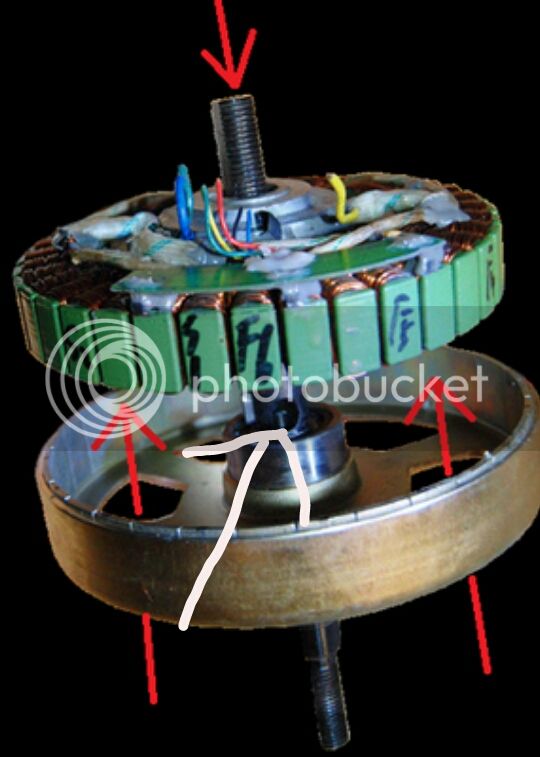
After staring at the parts I realize a simple washer between the stator and rotor would save the windings but would constantly grind and make noise because it would be sandwiched between two things moving different speeds. A tube that goes from the rotor bearing inner race to the case bearing inner race will keep the rotor safely away from the stator without making noise and grinding.
In keeping with endless sphere ethos I used the end of an old piece of shit handlebar as the stock to make the part.
mr.electric
10 kW
The tube will be about 35mm long. It goes from the rotor bearing through the hole in the middle of the stator and to the case bearing. There may be some other solution but this one seems simple and cheap enough.
b0b ,
Thank you for the tip on cutting grooves for c clips. I think I get the picture but I am not sure.
b0b ,
Thank you for the tip on cutting grooves for c clips. I think I get the picture but I am not sure.
Kepler
10 MW
Sorry to see things didn't go exactly to plan.
Can I ask why this issue wasn't picked up during assembly? Is it difficult to measure or judge the clearance when doing this conversion?
Great thread BTW and appreciate your's and of course Crossbreak's excellent development work here.
Can I ask why this issue wasn't picked up during assembly? Is it difficult to measure or judge the clearance when doing this conversion?
Great thread BTW and appreciate your's and of course Crossbreak's excellent development work here.
mr.electric
10 kW
It is hard to conceptualize how all the parts in these motors will interact. Counter rotating motor parts nested neatly together sealed in a can are so complex like the inside of a transmission.Kepler said:Sorry to see things didn't go exactly to plan.
Can I ask why this issue wasn't picked up during assembly? Is it difficult to measure or judge the clearance when doing this conversion?
Great thread BTW and appreciate your's and of course Crossbreak's excellent development work here.
The interference that damaged this motor only occurs when the motor shaft is plunged deeper into the motor. Since nothing really pushes or pulls on the motor shaft the issue did not present until the motor was driving a bike down the road.
dnmun
1 PW
is it possible that the shaft has bent and that caused the stator to rub on the hub portion on the one side. or if the drill press that drilled the hole for the shaft or the bearing mount may have been floppy when it was drilled, or there may have been some debris on the drill press table that twisted it as it was bored.
there is no quality control that would catch it, and there is no way some 17 year old girl who just moved there from the provinces and this is her only job would ever mention that it was a result of poor workmanship and would cull it. she would lose her job. so this may just have been a manufacturing error.
there is no quality control that would catch it, and there is no way some 17 year old girl who just moved there from the provinces and this is her only job would ever mention that it was a result of poor workmanship and would cull it. she would lose her job. so this may just have been a manufacturing error.
mr.electric
10 kW
The spacer tube did the trick. It goes where the white arrow is shown above. It ended up being about 12mm long. I had to open up the hole in the stator to clearance the tube as well. The tube rests on the bearing inner race that is visible behind the stator in the photo. I finally got a decent test drive! Really nice power band on this motor. The 6:1 reduction really makes it smooth and torquie. The motor still works well despite the hit it took in initial set up and testing. Fat tire front end install, pedal freewheel and odds and ends come next. I feel I could convert a motor in about 2 - 3 hours now having spent numerous hours in the trial and error phase. Thanks to Green Machine for supplying essential parts for the build.

.JPG")


bØb
1 W
Does the other end of the spacer rest against the inner race of the shaft bearing in the housing?
bØb
mr.electric
10 kW
Yes exactlybØb said:Does the other end of the spacer rest against the inner race of the shaft bearing in the housing?
bØb
Whiplash
1 MW
- Joined
- May 10, 2010
- Messages
- 2,906
Awesome congrats!! How is the sound from the motor now? My current drive is very quiet, did the conversion add any noise or would you say its the same as before the conversion?
Also, if someone were to make a new shaft, it seems that all you would need is a smooth 17mm shaft with the appropriate threads on each end no? I'm thinking a freewheel adapter on one end and some form of mount/thread for a drive sprocket on the other. I would think that would greatly ease the conversion if I was to do these in multiples for my up and coming frames if I am happy with the outcome. Very cool indeed!
Also, if someone were to make a new shaft, it seems that all you would need is a smooth 17mm shaft with the appropriate threads on each end no? I'm thinking a freewheel adapter on one end and some form of mount/thread for a drive sprocket on the other. I would think that would greatly ease the conversion if I was to do these in multiples for my up and coming frames if I am happy with the outcome. Very cool indeed!
mr.electric
10 kW
It is nice and quiet. It accelerates differently than a bmc in the wheel too. It feels like the motor has a bit more torque at higher rpms than when it was running in the wheel. The top speed in the gear I chose at random seems very similar to the bmc in the wheel. my front sprocket is a couple teeth smaller than the rear so i guess I am running a slight reduction. Since the frame stiffening is not complete I cant really nail the throttle because it causes chain slip. I have just gently rolled on the throttle durning my tests.
[youtube]LuDCl05uQRA[/youtube]
[youtube]LuDCl05uQRA[/youtube]
Similar threads
- Replies
- 18
- Views
- 791
- Replies
- 11
- Views
- 943
- Replies
- 12
- Views
- 10,857