CroBorg Super Commuter

Alan B said:
A few Highlights
looking awesome! i'm having a real jealousy problem that i think can only be solved by the purchase of one cromotor. :mrgreen:

it's been fasinating watching your evolution, i must say. from what, a year and a half ago, such a classic beginning... :lol:
Alan B said:
I have a pristine aluminum mountain bike that is a few years old.... I don't have a lot of free time so will probably not build much to start with but use good quality existing modules and kit parts... desire to be able to go 20 mph...
 
I'm having a lot of fun, Greg. Thanks for your early encouragement. A lot has happened in a year and a half. My wallet is lighter too. I need to ride these things a whole lot to recover the savings in gas...

There is something about riding a bike you "made" that adds a lot to the experience.

What is the cost of an ebike addiction?

Less than golfing, flying, yachting, hot rodding cars, and a few dozen other hobbies.

What is the value of the ebike grin?

Priceless.. :wink:

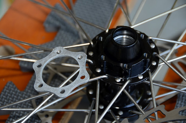
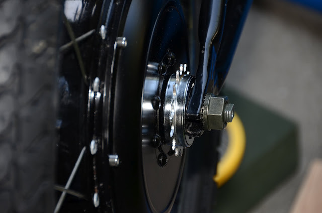
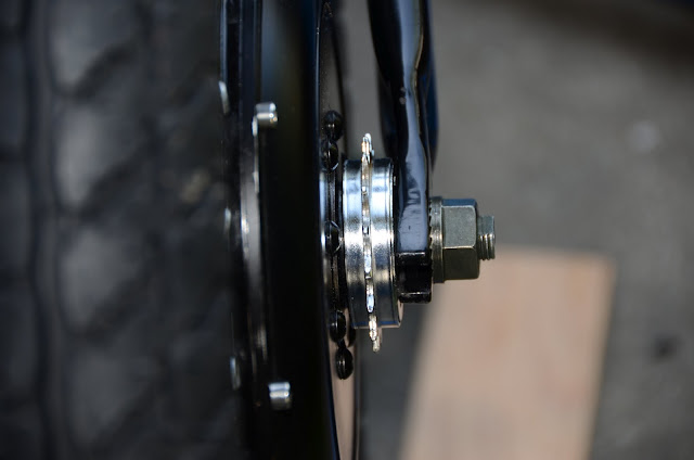
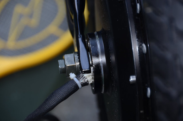
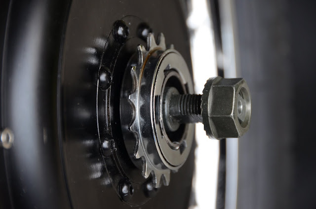
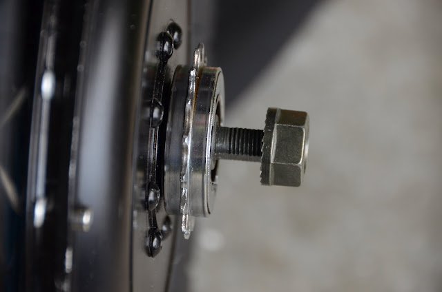
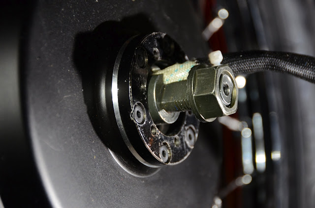
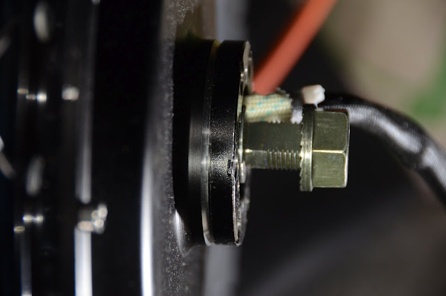
Stevil made an observation on Sunday when looking at his versus my Greyborg rear wheels. They both have the same tire, the 17 by 3" Gazelle moped. His Xlyte HT3525 disappears behind this fat tire. The beefy Cromotor is visible on both sides of this tire. I won't need a spacer on the freewheel to make the chain clear the tire :) But I will still need a small spacer to make sure the freewheel and chain clear the motor.

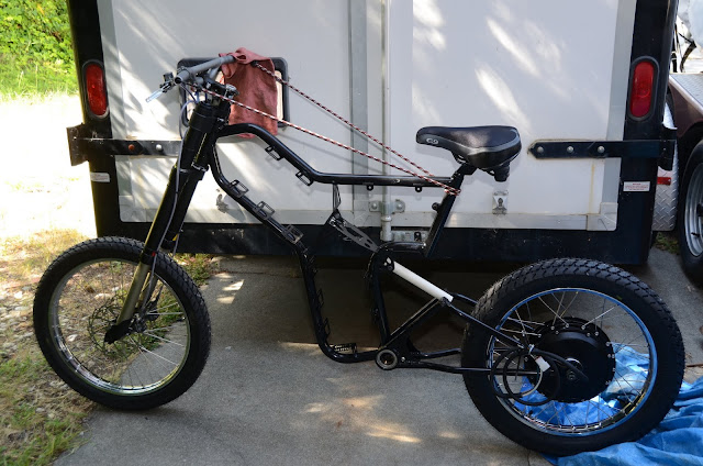
I tested the 3" tire in the Swagman bike rack. No problem fitting into the tire hoops. Hopefully the weight won't be a problem either.

On to the current issues:

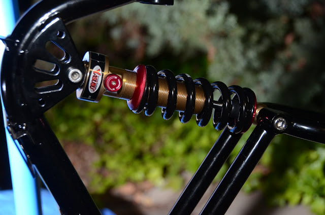
I'm working on ordering a rear shock from Yasusu. As suggested by Hal - the Model BNCP401, 170mm long, 30mm bushings both ends, 8mm bolts, 90kg rider weight. Stevil has a shorter 160mm long rear shock, but his cranks are also shorter at 160mm. My cranks are 172.5mm so I want a slightly longer shock. I'm guessing that this won't be the last shock I buy, but I need something soon to start with. The order is not quite in place, we're exchanging some email to set it up. Should be on order very soon.

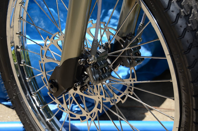
I'm also ordering spacers to move the dual front discs out away from the spoke-caliper interference. Hopefully 2.5mm will be enough. The other option is to go to larger discs, these are 160mm. The problem with going to larger disks is finding the mirror image caliper adapters. With duals I hope 160mm is enough disk area (at least for my riding style, Luke would melt them in seconds). It is sort of like a single 320mm disc. The problem is the caliper width is enough to touch the spokes now. It is hard to judge but 2.5mm may well be enough to clear it. Ebikes.ca have a 2.5mm spacer that I'll try first.

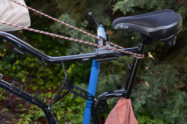
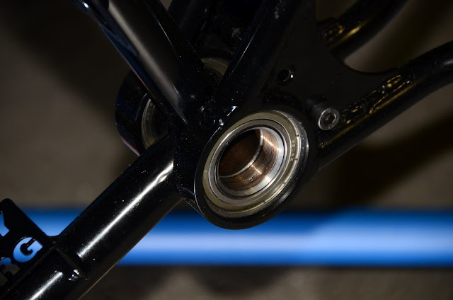
The next big step on the frame is to fit the crankset and swingarms. This ATS Schlumpf requires bevelling of the bottom bracket tube with a special tool that Ilia of ebikessf.com has, and it looks to me like this needs to be done before the swingarms are installed. Then the swingarms must go on before the crankset is installed with the special tools. So I need to be prepared to install the swingarm in the midst of the Schlumpf install, or rent the tools.

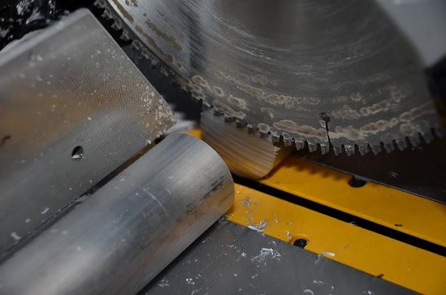
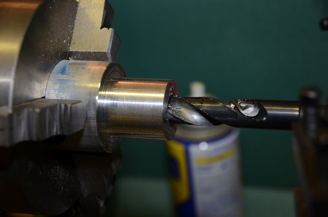
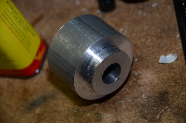
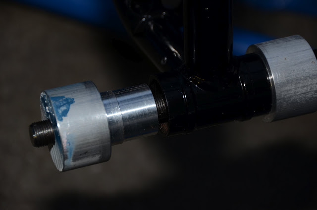
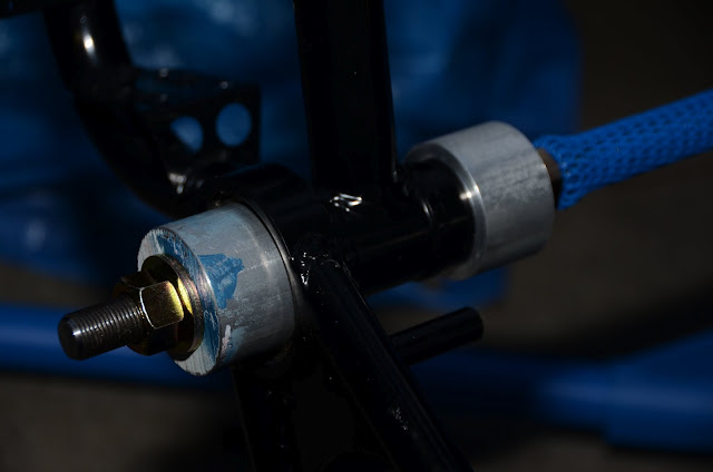
Some folks sand off the paint and make the swingarms slide on. Others press the swingarms on without removing the paint and get a tighter fit. Seems like a tighter fit here is good. So I'm planning to do that. Perhaps remove a bit of finish at the outer edge to help things start straight, but not all of it, and it will be very tight. To push the swingarms on properly I'm planning to make a tool. I have some two inch diameter aluminum bar stock that is just about the right size for this tool. I'll chuck in the lathe and turn a diameter to fit in the bottom bracket and make a shoulder that will push on the inner race of the bearing so there will be no force on the bearing balls etc. I ordered a threaded rod so I'll center bore a hole through a pair of these turned bar sections and make a custom Greyborg swingarm installation tool. Then we can seat the swingarms on efficiently and straight when it is time.

At least that's my current plan. Any comments would be welcomed!
 
A few bolts are needed to put the swingarm together. Looks like:

2x M8-1.25 by 20mm button head for the threaded studs.

1x M8-1.25 by 45mm for the shock upper end, plus nylock nut and two washers for the outside (inside is bushings and shock).

1x M8-1.25 by 60-65mm socket cap for the shock lower end, plus lockwasher, goes into threaded socket in swingarm, (inside is bushings and shock).

4x M6-1.0x12mm with washers and nylock nuts to tie the two sheet metal flanges together.

1x M8-1.25x20mm socket cap for the seatpost clamp.

Stevil used a quick release skewer through the seatpost clamp and that is one nice technique. In that case it needs to be thin enough to slide through the M8 threads, or use a 20mm socket cap screw and perhaps put a hole through the plastic to reach it, and a rubber plug in the hole.

The threads are a bit filled with powdercoat/paint so they need to be chased with a tap and lightly greased to prevent rusting.

edit - updating per further comments and measurements.
 
Are bolts metric or imperial?

I was under the impression that needed bolts measured in inches.
 
Stevil gave me some that were metric, presumably that's what he used in his. Wouldn't expect Hal to use inches.

But I'm not 100% certain.

Hal's list doesn't have all the measurements, but the ones that are there are metric. When I test metric bolts in the holes they don't get very far, it is either the paint or the threads.

I'll do some more checking and see if I can verify it.

Anyone else know?
 
Alan B said:
A few bolts are needed to put the swingarm together. Looks like:

2x M8-1.25 by 20mm for the threaded studs,

2x M8-1.25 by 50mm for the shock,

4x M6-1.0 by short with washers and nylock nuts to tie the two sheet metal flanges together.

I need to look at the seatpost to see what it needs. Stevil used a quick release skewer through the seatpost clamp and that is one nice technique. In that case it needs to be thin enough to slide through the threads.

The threads are a bit filled with powdercoat/paint so they need to be chased with a tap and lightly greased to prevent rusting.

Hey Alan,

Yes, Metric -> the threaded studs and shock mounting bolts are indeed M8-1.25. Looks like your #s are correct, but I measured ~60mm long for the shock's lower allen cap screw/head bolt. Optimally, all the other bolts would be button head.

Got a good feeling that those rotor spacers are going to do the trick..

..26 of 25 - be efficient
images
:lol:

http://www.imdb.com/character/ch0001490/quotes

"Star Trek: Voyager: Dark Frontier: Part 2 (#5.16)" (1999)
Borg Queen: We are Borg.
Seven of Nine: I am an individual!
Borg Queen: You're only repeating their words. You sound like a mindless automaton.

Borg Queen: You've changed. Your exo-plating, your ocular implant. They've taken you apart; and they've recreated you in their own image. Hair, garments. But at the core, you are still mine.
Seven of Nine: The Borg have changed as well. I expected re-assimilation, not conversation.
Borg Queen: I see they've also given you a sense of humor.
Seven of Nine: My humor is my own.
Borg Queen: Spoken like a true individual.

Seven of Nine: I am Annika Hansen, Human.
Borg Queen: I remember Annika. Does she remember us? She wasn't afraid. Why are you?

Borg Queen: We won't turn you into a drone. You're much too valuable to us with your individuality intact. But you've left humanity behind. Try to abandon their petty emotions as well. Fear... anger... vanity... They've corrupted you. But the damage can be repaired.

Borg Queen: We want you to be our eyes. Let us see Humanity.

Borg Queen: We don't want another drone. We want you.
Seven of Nine: I will resist.
Borg Queen: I know.

Borg Queen: Stop resisting. Take pleasure in this.
Seven of Nine: I will not take pleasure in the destruction of a race!
Borg Queen: Human sentiment. Compassion, guilt, empathy - they're irrelevant.
Seven of Nine: Not to me.
Borg Queen: "Me"? There is no 'me'. There is only 'us'. One mind.
Seven of Nine: My thoughts are my own.

Borg Queen, Seven of Nine: [respectively] Our thoughts are one.

Seven of Nine: You attacked us. You murdered my family!
Borg Queen: We did no such thing. We gave them perfection.
[one Borg steps forward into the light]
Seven of Nine: [aghast] Papa...?

Captain Kathryn Janeway: Let her go, or I'll give the order to fire.
Borg Queen: You would be destroyed as well, along with your crewman.
Captain Kathryn Janeway: Better than being one of you!

Captain Kathryn Janeway: Seven, shut down that field.
Borg Queen: Don't listen to her. She's poisoned your thoughts long enough.
Captain Kathryn Janeway: [to Seven] I'm giving you an order!
Borg Queen: One order, one voice! Insignificant!

Borg Queen: Seven of Nine - be efficient.

:arrow: http://www.gorillavid.in/cnb/ajh12r9a1xgn
 
You are right about that swingarm shock bolt length. 65mm will even fit. I updated the earlier post to make it correct. Thanks.

Tonite I chased the threads with M8-1.25 tap and that's the right size. It fit nicely. The threads are now ready.

Some of the parts came in, the all thread for the swingarm press I'm making; the 16mm NordLock washers; a small flap sander to clean out the seat tube with. Still waiting for the disc spacers.
 
Front rotor spacers are in. Dual front 4 pot Gatorbrakes are on. They clear the spokes, which is the important thing. I need to find more spacers to get the calipers centered, but they will work now, they just drag slightly on one side.

The seatpost is another story. Very disappointing. A couple of hours of working on it and only about 1.5 inches of progress. My back is sore, enough for now. Tolerances are tight, and then welding distorts the tube, not easy to fix. Have been sanding out the inside of the tube. More to go.
 
When something is not working out, it is probably due to the wrong tool, the wrong technique, or both.

I'm a lot happier now than a few hours ago. :D

I was using a 1" by 1" flap drum on a 4" mandrel with 80 grit driven by a Makita 18V drill inside the seat tube. This is a nice tool but not efficient for this. I picked up a 1" 60 grit sanding drum, and I switched to a 1/4" air driven die grinder. It spins a lot faster than the drill. It still took awhile, but I was able to get 8" of seatpost into the tube. I finished up with the 80 grit flap disc, it leaves a very nice finish in the tube. It fits down to the level of the bottom weld on the seat tube. So I cut the seatpost to 8" long and installed the seat. Finally!

The seat clamp is M8 by 20mm.

Next I took the 2" diameter bar of 6061 Aluminum and ...

More later...
 
Progress Report

DSC_9213.JPG


Ebikes.ca 2.5mm disc spacer. Just what the doctor ordered for this caliper hitting spoke problem.

DSC_9222.JPG


Dual mirrored four piston Gatorbrakes on 160mm dual discs. 320mm of stopping power. And not hitting the spokes!

DSC_9225.JPG


Finally! The seatpost is 200mm into the seat tube. Whew!

DSC_9226.JPG


Chopping 2" 6061 bar stock. Not a recommended procedure. Requires a high tooth count aluminum cutting blade and a stiff chop saw and a slow cut. Could be quite dangerous if something goes wrong. This is the same technique I used to cut the 24 FET controller's extrusion shorter to fit in the frame.

DSC_9227.JPG


Chuck it in the lathe, turn a shoulder and bore a hole to fit the all-thread.

DSC_9230.JPG


Make another for the back side, this one doesn't need a deep shoulder.

DSC_9234.JPG


Testing on the frame. Ready for use!

DSC_9235.JPG


Here we go! Pushing the first swingarm onto the frame. Hope these never need to come off. They're snug. Very snug.

Both swingarms are on, enough for one day. Need to rest my tired back.

Progress feels good. It is almost a roller. :D
 
Measured natural rear dropout spacing, 130mm. This may vary a bit from one unit to another.

It is going to be tight to get the Cromotor in there. It needs a bit more space than that. Especially for a rear disc brake.

I test fit the motor. It fits, with a slight springing out of the dropouts, perhaps 5mm. The shoulders on my Cromotor axle are not quite wide enough so I will have to make spacers to keep the dropouts from rubbing on the brake mounts and freewheel.

I made a temporary "shock" of PVC pipe. At 170mm it is a bit short, I may go with a slightly longer one.
 
DSC_9242.JPG


Dicta freewheel is flush with end of motor threads, has run out of threads to turn it on farther but needs about 2.5mm freewheel spacer to rest against so it is not against the end of the threads. (edit - wrong, the freewheel is resting on a shoulder, no spacer is required or desired).


DSC_9243.JPG


Dropouts touching freewheel. The motor shoulder is just about the same height as the freewheel threads so an axle spacer is needed. The usual ones don't fit these 16mm by 10mm axles, so "C" washers with OD of about 25mm need to be fabricated.


DSC_9244.JPG


Dropouts touching brake mount even without disc installed. "C" washer needed here to allow cable clearance and space the dropouts out.


DSC_9245.JPG


It's a roller, sort of. :)

Need some spacers.
 
Pedal drivetrain progress Update

Took a visit to ebikessf.com today. ilia worked on the ATS Schlumpf drive installation. The bottom bracket shell is nicely chamfered now, but the body of the drive touches the ring around the swingarm bearing. So some cone washer spacers need to be ordered.

The chainring is also fitted, which means that the drive's bent ear has been coaxed into alignment. Need to find the proper tool to tighten the chainring bolts...

ilia was impressed with the forks and the frame.
 
Freewheel Spacing

I previously measured 2.3mm of space between the freewheel and the body of the motor. Today I tested a 2.25mm spacer there, and it pushed the freewheel out well beyond the end of the freewheel threads. Turns out the Dicta freewheel was already contacting the shoulder. The space I observed was at a larger diameter. So no spacer is needed or useable in a practical sense.

I didn't remeasure the freewheel versus end of threads, but it appears that the freewheel hangs out a fraction of a mm farther than the threads. So there is no point in trimming the threads back to get more room, the freewheel is the widest element now. A "C" or "D" washer is needed to keep the dropouts from rubbing on the freewheel.
 
Freewheel Info

I tried to measure the freewheel edge to end of the Cromotor's threaded freewheel mounting tube, and it is essentially flush. I also tried to measure the inset of the axle shoulder, and it is not easy to measure, but it is very slight. I didn't get a good reading, but it appears to be a small fraction of a mm. So I gave up on measuring them and took some photos:

DSC_9309.JPG


DSC_9311.JPG
 
Hey Alan- Love the photos- great combo of pretty parts and good camera/technique :)

Looks to me like the FW side could use regular flat washer(s) between the axle shoulder and the dropout- 5/8 nominal size would likely work out fine- does this seem right or reasonable to you?

When I'm making up the prototype C washer out of aluminum, 1" OD, what would the most optimal thickness be? Still ~2.5mm? I may be able to do this before the end of the week, for dead certain before the end of next week.

-H
 
A regular washer should work, though it doesn't get quite the shoulder support that a "D" or "C" washer would.

I grabbed those pics this morning before I went to work, I'll try the same on the flip side in tomorrow morning's light and verify spacing. How much clearance between the hub and the dropouts is prudent? The dropouts are about 130 mm and the motor is wider than that, so I will be bending dropouts outward slightly. I'm trying to minimize that but we need enough clearance.

OK, I just went to the garage and used a flashlight plus an off-camera slave flash to get some shots of the wiring side of the Cromotor. There is a bit of axle shoulder beyond the disc brake flange. Aboutn 1mm. So the washer needs to be disc plus screwhead thickness plus dropout clearance minus the approx 1mm to work with a disc, or just a couple of mm to work without a disc. I don't have the rear disc to measure yet, and I don't know how the disc is going to line up with the chainstays. Ultimately it might need a bit more washer width, but this might decenter the tire if it gets too wide.

So 2.5mm is about right for no rear disc, but more is needed for the rear disc. I don't have to start with clearance for the rear disc, though it might be smart to start close to that.

Here are some quick shots of it:

DSC_9325.JPG


DSC_9323.JPG
 
The Yasusu package was shipped 3 days ago. Amazing!

The shock is installed. I had to grind the shock mounting plates a little to clear the shock top flange.

I also had to shorten the bushings on the low end of the shock. My swingarms are a little tighter than Stevil's, I should have used my dimensions instead of using his on that part. His were 30mm spacing, mine 25mm.
 
After returning from the Maker Faire I set up the Borg and re-spaced the front calipers, ending up with 2.10 mm of spacers.

Then I changed over the temporary steel bolts for stainless on the swingarm.

I tried a 5/8 washer on the motor's freewheel side and the OD is too large so it hits the threaded freewheel tube. The washers are needed to install the hubmotor wheel.

I reviewed various techniques for seating the star nut in the steering tube. I'll probably get a piece of all thread and make a tool to pull it in. That looks like the best technique.
 
Back
Top