Crystalyte Controllers - Repair and Modification information

Hi guys,
I have Deecanio's Puma Controller on the bench here, story is, Knoxie tested it, then when done sent the working controller to Deecanio.
Upon arrival, Deecanio could get nothing working.

After testing it through, I found no blown FET's, or otherwise damaged components.
However, whilst testing the halls wires, I find that the red is at 5.1v, black at 0v, and all other wires at 5.72, regardless of whether or not the halls wires to the motor are connected or motor position.
Any suggestions as to why this might be? (I realise that noone knows anything about this controller yet, but am hoping for a few pointers on where to start looking for the problem)


Thanks all....


Steve
 
Try disconnecting the halls and measure the voltage between the red and black wires coming from the controller (power on).

The older crystalyte controllers ran around 14v open circuit to the halls, and around 7-10v with the halls connected.

I don't know how you can get 5.72 on the outputs if the supply is only 5.1v

It almost sounds like the hall wire colors got mixed up.
 
I'll try that tomorrow. I measured voltage from the PSU's negative terminal, and on the board rather than the wire ends. T'is indeed strange, but noone has tampered with the wires since Knoxie had it working, and wiring all matches the other controllers here.

The 5.72v was measured on the hall connections in the controller whilst the motor was NOT attached also. I'll post more info tomorrow...


Thanks,

Steve
 
Ok, with the halls disconnected, measuring from black to red I get 5.1v, and from black to any other halls wire 5.72v.
Any idea's where to look for the problem? why would it be putting out +volts on the inputs?
 
Hi

Why didn't anyone mail me? first I have heard of it??

It sounds like its ok, have you checked to see if the halls in the motor are firing? connect the controller up and spin the wheel backwards, you should notice the outputs going high, use a scope if you have one if not a DVM or preferably an analogue meter is the next best thing.

They are different to the xlyte controllers as they sink high as Richard has mentioned, these may only operate on 5V, the hall sensors will operate ok at that voltage.

Have you tried it on one of your motors you know works? have you compared it to your Puma controller? double check the wiring against a working example to make sure they are connected the same.

That controller worked like a charm when it left me, I still have Marks other controller here that I can power up and test to see how it compares, I will go and do that first then report back.

The phase connections to the stamped BMC were an unknown as I had not connected them however with only 3 x connections it doesnt take long to work out the right order.

Off out in to the garage now with my DVM.

Cheers

Knoxie
 
Jozzer said:
Ok, with the halls disconnected, measuring from black to red I get 5.1v, and from black to any other halls wire 5.72v.
Any idea's where to look for the problem? why would it be putting out +volts on the inputs?


I used the old Xltye controller to replace the stock Ananda controller for my folder ebike for upvolt to 48V (from 24V).

A) Ananda controller.
When disconnected:
From black to red about 5V;
From black to any hall wire (yelow, green or blue) about 5V.

When connected:
From black to red about 5V;
From black to any hall wire (yelow, green or blue) will alternate between high (about 5V) and low (about 0V) when the motor rotates.


B) Xltye controller.
When disconnected:
From black to red about 13V;
From black to any hall wire (yelow, green or blue) about 13V.

When connected:
From black to red about 7V;
From black to any hall wire (yelow, green or blue) will alternate between high (about 13V) and low (about 0V) when the motor rotates.

Note that the phase sequence of Ananda and Xltye are different.


You readings for hall wires are similar to my Ananda controller when disconnected.
The hall wire has about 5V (when disconnected) due to an internal pull-up
resistor.

What are your readings when connected??
 
Even if the halls are firing (and they must be, since the motor works with another controller), the return voltage cant be seen by the controller because there is already a higher voltage on the line....

The7, connected or disconexted makes no difference...theres a higher voltage on all wires than there is on the red, regardless of motor position, and constantly. I just tested my x'lyte controller, and you are right about the voltages on the other lines with the halls disconnected...how can this work?

I've traced all the wiring and checked all connections again just to be sure, but including Andies motor, its now been connected to 4 working Puma's and 1 x'lyte motor with no joy.
 
Hi

I just tested the new controller, with no motor connected there is 5.3V on the red, and 5.6V on all hall wires, this indicates that the sensors in the wheel are sinking this voltage back through the controller when they fire.

So with it all connected and rotating the wheel backwards against the freewheel (making the rotor spin) these voltages drop from 5.6V down to zero alternatively, that indicates that all the halls are working correctly. Split the controller and check for continuity between the plug and the board on all wires first.

Its early days for the Puma controllers and they havent been tested ala the xlyte controllers to be fair, this is all part and parcel of it in many ways.

I didnt do any testing with the old BMC stamped motors however just the new ones, I think part of the problem with the Pumas when running on higher voltages on some controllers is the emf caused by the freewheel, on a xylte motor this is not an issue but there is a considerable amount of stored energy (magnetizing current) in the rotor as it decelerates that may be causing problems at higher voltages, harmonic issues and high pulses are bad news for the fets if not properly protected, I don't know as my Puma on my main bike has been running on a standard untouched xlyte 35A 48V controller for nearly a year and used everyday?

I still think this is a wiring issue? possibly, my analogue electronics is pretty good so I can pin one down and snoop about with the scope when I get time, let me know how you get on Jozzer, Richard will no doubt be able to fully cast the light on it as he is rather clever in that department!

Cheers

Knoxie
 
Excellent, thanks for the tips. Once I stopped thinking that the higher voltage on the other lines was to blame and started looking more carefully I found that the negative lead had a dry joint on the board end. Resoldered it and the other lines dropped thier voltages as they should.

After swapping some phase wires and snipping the reverse cable We have a controller running on the old puma motors.

Happy days Andi....i'll post it back to you tomorrow!

good work guys, thanks :D


BTW, usefull bit of info, the new Puma's are colour co-ordinated the same as X'lyte. So are the Puma controllers. If (like Andy) you will be attaching the new puma controller to an old motor, you connect the phase wires as follows..
Controller Blue to motor yellow,
Green to motor blue,
yellow to motor green.
 
Jozzer said:
started looking more carefully I found that the negative lead had a dry joint on the board end. Resoldered it and the other lines dropped thier voltages as they should.

:D
Good work 8)

That's bad. Was that in the motor or controller?

I suspect that even a breif disruption of the hall signals while the motor is running can cause instant FET destruction if a phase switches out of sync with the rotor. Cheap connectors are very bad here.

It would be good if the controller was fault tolerant to loss of hall signal.
 
It was on the board end.
Perhaps Deecanio should change from these cheap din plugs though, they don't look that reliable to me...

i wonder if similar problems have killed the other controllers?
 
Hi

Thought as much! I even thought it may be on the negative wire as well! but nobody likes a smart ass :lol: The other reason I asked you to check was because DC split the controller apart and I didnt so it may have wiggled the wire and exacerbated the problem? bad joints are a pain.

Loss of hall may cause fet shoot through, I dont know how or if they are protected, Richard may be able to tell us more, I must admit I liked the Puma controller as well, I must install it on to my main ride and give it a good shake.

Glad that you have got it sorted though.

Knoxie
 
The IR2101 will prevent shoot through on any particular phase.
The problem is if a phase turns on in the wrong sequence, the BEMF might be totally opposite of where it is supposed to be, resulting in a major current spike.
This would be like running the motor full speed, then suddenly hitting reverse. The inertia of the rotor will be able to source hundreds of amps long enough to fry your FETs.

Ideally, the commutator chip would provide protection against this, but I don't think it does.
 
Hi Richard

OK right, the trouble is they have sanded off a lot of the component identification marks as usual, however it may be possible using the xlyte controller as a guide to see just how they have implemented their BLCD control.

Lets hop DC gets back up and running soon.

Knoxie
 
No part numbers?
I don't need no stinkin part numbers.
We'll see what it does.
If the problem turns out to be something in software, it might require getting a copy of the code. I'm not sure if those microcontrollers can be read.
 
Mark can and will get ahold of any info you need regarding software and chip info. He already had a shout at them for rubbing off the numbers :lol:
 
Hi Guys,

tried to wire up again today but alas i'm getting a big fat nothing from my bike :cry:
im going to check what i can but if you guys have any tests i can try post and ill read then try it.........
im not sure whats going on as i really thought i'd plug it in and be away today - i have to admit though in my rush i fookin dropped it :oops: it fell to the deck from a foot or so and i thought to myself if it doesnt work now im gonna look a right twat.
anyway confession over - help!!!!


cheers


D
 
Andy, check that those halls wires are making proper contact, more than half the time that plug doesnt mate properly. Try and push the pins further in with a small screwdriver, or better yet, take off the connectors and solder it (or even twist them and tape them carefully for a test).
 
Solder them. Don't screw around with dodgy hall connectors.


It would be cool if the controller had 3 led indicators for the hall signals. This would not be hard to add.
 
hi guys,

yeh i thought the mini dins might be pants but i took all the connectors off and simply have the pins connected into each other?
i've tried all the phase connections too - im starting to think i broke it but i cant believe a small drop would kill it? ive hit harder bumps than that!!
oooh i oculd try a new throttle?
i could try the xlyte controller but id have to stip back the hall cable to see the colours as i didn't write them down?

Cheers


D
 
went to disconnect the throttle and two cables popped out of their connector on the controller side :(, ok i'll fix that then try the new throttle :?


D
 
Deec, unless you mean you have each individual pin out and connected, it still is fussy. If you still have the 5 pins in the little black holder, find the back of each pin and give it a nudge down.
If you really mean that you have stripped all 5 bits of metal out, then, I guess its not that:(
 
Anyone have any advice for adding the direct plugin connector to a crystalyte controller?

Justin was kind enough to sell me the 6 pin connector with my Cycle Analyst so I could add ity to my dual speed controller, but the picture of the 20A controller from his website isn't the same version as the one in my dualspeed.I can probably figure it out, but I'm second guessing my self. has anyone tried this before, or have any advise on wiring into the Clyte 72v20a controller?
 
hi all,

Thanks to Jozzer's troubleshooting over the phone (cheers mate) we did manage to get the controller running last night :) yayyyyyyyyyy!!!!!
ok lots of cabling and tidying to be done today but i'm hoping to get out later and have just a road ride to see what 72v can do!!!
will check in later and hopefully, hopefully the DC1 will break 30mph today!!!


cheers


D
 
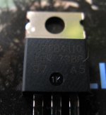
I finally received 150pcs. IRFB4110. 60 went to some of you who wrote me earlier, 30 I keep for myself, rest is still for sale here in the UK.
The price is £2.3 each mosfet plus postage (first class £1.5 or better... special next day delivery insured up to £500 for £4.30)

Get the best 100V mosfet on the planet fast ! Last 60 available!
Why I ordered 150 and selling them?
The aim was to get them to UK and share the postage/vat/ import tax when getting them from the USA.
 

Attachments

  • irfb4110.jpg
    irfb4110.jpg
    188.8 KB · Views: 807
Back
Top