Definitive Tests on the Heating and Cooling of Hub Motors

More designs to consider for air cooling?

Mine are a case of a bit here and a bit there....

(from my bike thread)
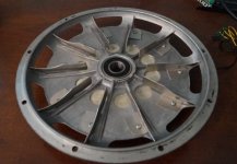
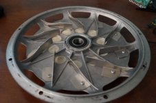
The motor was second hand and had some holes drilled in the freewheel cover (which I took out to the outside edge) so I drilled some more in the brake side with a slightly different design.

I also chucked an impellor from an old vacuum cleaner on the brake side- I was thinking it might help direct some air into the intake holes which are drilled underneath it near the axle. This is designed to fling air from inside to outside and I'm using it in reverse so who knows what will happen- it's also spinning a lot slower than design speed.

When I did a smoke test with it this evening, it appears to suck a little bit of the smoke in but with no baseline to work with I'm not looking for improvements, just whether it works at all as I'd like to put 3-4kw through it.

20130407_142229.jpg

20130407_142239.jpg


The untested vaccum impellor:
20130407_153837.jpg

20130407_153857.jpg
 
Great work Justin :D

here's what i did, trying to exploite venturi effect and turbine effect.
file.php

Its not definitively tested yet though. ill have to hook up the thermistor to the ca and run tests with and without tape over the holes.

Venturi effect pic from Wikipedia.. air blowing over the holes pulls air through the holes. Im not sure how many people understand this.
300px-Venturifixed2.PNG
 
John in CR said:
I won't get data like Justin, but stator temps pumping 25kw+ peaks into the motor on long rides and big climbs will have to suffice. That may seem contrary to my statements above about max power, but at 210A battery side limits the motor didn't show signs of saturation. That was at 20s, and my new controllers allow me to go to 32s, making 25kw input a certainty as long as torque throttle works with my dual controller rig. It won't be continuous, but still meaningful results. :mrgreen:
John

Looking forwards to your results, John!
 
pendragon8000 said:
Great work Justin :D

here's what i did, trying to exploite venturi effect and turbine effect.
file.php

Its not definitively tested yet though. ill have to hook up the thermistor to the ca and run tests with and without tape over the holes.

Venturi effect pic from Wikipedia.. air blowing over the holes pulls air through the holes. Im not sure how many people understand this.
300px-Venturifixed2.PNG

Not many here do understand it (unfortunately). However, it seems like the "vanes" whether inside or outside should lessen this pressure difference between the top and bottom holes. I'm not even sure how you could test/visualize/confirm this, since a real world motor would have air flying past it at high speed, while holes at the top of rotation would have even higher wind speeds.

I'm very eager to see the liquid cooling results at varying liquid amounts.
 
The venturi effect will attempt to pull air out of any holes on the cover, more so at the outer portion due to higher rotational speed as mentioned above. That's why it might be a good idea to have some form of scoop or fan helping direct air into the intake holes rather than letting the air go past them -which is what I was trying on the braked side of my motor.

Having said that, smoke definitely appeared to be sucked in to the plain holes on the freewheel side of my motor- but this is during a static test with the wheel spinning at full speed and no airflow past it. Aaah, nothing like commenting on totally unscientific testing without any baseline or repeated tests. I did it once after having consumed several beers. :roll:

Sorry for the excessive thread contamination Justin! We're just all killing time waiting for some more test results! :mrgreen:
 
Shall I be first to say how poor my scoops idea was. Even with careful positioning and a narrowing of the intake scoops and widening of the exhaust, It really needs a target to work on, such as a heatsink. It wouldn't help at all if the idea was venting through small holes. Even if it were sealed to them to produce effects similar to the models above with there perfect trading of volume and speed in that sealed duct.

Pics of the brackets that broke after drilling would be good here, to explore slots rather than holes, as it appears people have already done.

Are outer case mounted magnets generally glued with a proper heat sink epoxy? I have some 'arctic silver' 2 part epoxy thermal adhesive here that might be beyond the cost of cheap manufacturing, but ideal for home rebuilds. The magnets are very close to the stator so if you thermally bond them to the case and them bond a heatsink to the outside of the case, you have an attractive route for heat to leave the stator. The ir emissivity of some treated metals can be quite low, so maybe blackening there surface would be a good idea. No heavy coatings, but a marker pen is in theory going to help things. Cooling the case comes back to a fan as a moving heatsink. I reckon this fan idea has merit.


Uploaded with ImageShack.us

The fan may draw hot air away from the hub, but so does the breeze. This fan should be fairly thick plate as it's to conduct heat out from the core. The fins just keep the heatsink cool to draw heat from the core.

You could get silly with an ultrasonic mister, or simple spray nozzle. Atomised water will try to turn to vapour, cooling the air around it. What does hit the fan will further aid cooling, like a wet finger in the breeze. Damp sponges? now I'm getting silly again...
 
Spicerack said:
Sorry for the excessive thread contamination Justin! We're just all killing time waiting for some more test results! :mrgreen:

This is more entertainment than contamination Spicerack, so no worries there!

Additional test results are all completed with the milled out side covers, and I'm just going through the somewhat time consuming process of making it all presentable in tidy little graphs for your digestion pleasures...
 
My thanks for your time and effort on this. Making it all presentable and tidy is icing on the cake, and I'm sure you will be adding it into your own presentations. A gold mine of info! I can't wait to see how well the oil cooling helps vs open sidecovers. The additional thermal path should really increase those side cover temps. Now I wonder how the sidecovers can be modded for better heat shedding. Bead blasting? Ridges? A few little pin style heatsinks glued on to shred up the air and any unsuspecting legs?

I'm working on a prototype motor that sits at stall most of the time, it is a force feedback system. The original motor burns out after a few hours, and larger replacements get heat soaked after 30 minutes and lose half torque (ceramic mags). The person funding the work has already put in tons of effort to air cool and pull heat away, so we are left with oil bath and heatsink as the last resort. My hardest task has been finding oils that don't contaminate commutators, as we can't retrofit a brushless motor without serious hacking into the system. Otherwise a very similar project in concept.
 
Great Work Justin!

I love it. Debate is cool and all for getting the ideas fleshed out knocked down and as a teaching tool but data...mmm...loves the data. Thanks for doing this. I really appreciate your methodology. I lack the resources (particularly time, money, intelligence?, equipment) as do many, but giving your time and resources like this to answer these persistent questions is really awesome.

I voted with my actions on this topic. I went with oil bath. I mounted two straight brass 3/4" flare nut fittings at fairly extreme angles to create a good interior opening size and geometry, with two sections of 3/4" copper tubing, (although I am considering 1" for the future), moving ATF out the sideplates, between the spokes along the contour of the motor to a spot nearly diametrically opposed on the other side cover, where it re-enters. The tubing is housed in an aluminum lamination of multiple layers of flashing, with a sequence of 3 layers creating a fairly solid base in contact with tubing/thermal paste, alternating with one layer extending out radially several inches. Huge amount of surface area.

I started a thread on this some time back, but I have been extremely busy. I have good pics,video and equations, and it seems quite effective. It increases the amount of oil which can be used pretty significantly, and consistent with Fourier's Law the amount of area used to conduct heat expands dramatically. I know a picture is worth a thousand words, however, I have a huge favor to ask. I know it is not fair to ask for any more of your time, but if you would sell me a couple the sidecovers, I would love to make the modifications, and send them back to you so that you could put them on one of your oil cooled hubs, and compare. I would love the data to be generated in a consistent methodology (which I lack).

Also, the guy here in the US with the EERE nod seems to be the Grainger Professor of Electrical Engineering at the University of Wisconsin:
-
Thomas Jahns
2559 Engineering Hall
1415 Engineering Drive
Madison, WI 53706

Ph: (608) 262-5702
Fax: (608) 262-1267
jahns@engr.wisc.edu

He may be good to talk to. I hope the sphere does not bomb the guy with a bunch of drivel, but a level of methodology Justin has here, would likely spark his interest. No problem if you do not want to open Pandora's Box of submitted cover modifications, but I really like what I am seeing, and I think you will too.

I like what you said about Aluminum Stator and the heat capacity. But ultimately all that heat still must be transferred, not just buffered. Although combined with something like your CA able to decrease current in response to temperature it is a good solution.

Enjoyed the air cooling discussions so far. I think John's point on turbulence is largely about whether laminar flow on either side will generate relative dead zones in the winding heat topology (at least in my mind *my questions...not the dead zones). 6 of one half dozen of the other. Looking forward to Oil!!
 
Sancho's Horse said:
I think John's point on turbulence is largely about whether laminar flow on either side will generate relative dead zones in the winding heat topology (at least in my mind *my questions...not the dead zones).

I prefer to keep explanations simple and not cloud issues with technical jargon. Let's get really visual in this case. You're sitting in your work room with a fresh cup of coffee in an insulated cup. The wind is blowing outside and you have open windows at both ends of the room, so there's some air flow through the room. You take a sip and the coffee is way too hot. You can even feel some heat on your face as it rises from the cup. Then you blow into the cup and can literally feel many times the heat on your face being released from the coffee. The room is your motor. The coffee is your windings, where most of the heat is generated. The flow through the windows is the modest flow you've worked hard to create by putting holes in your motor, which is going to take the path of least resistance to the exhaust window. Blowing into the cup of coffee is the effect I try to create with interior blades (increasing velocity and turbulence at the surface of the coffee to greatly increase the convective heat transfer coefficient), along with ensuring full rpm of the interior air so there is a good flow of fresh air.

I need to go look at your oil cooling. When I looked before, I didn't see a mechanism to force a flow of oil through the tubes during operation. If it does actually flow instead of get forced there until the next stop, and you've made it leak proof, then it's the going to be the cat's meow of cooling. A few have tried liquid cooling, but ran into too much resistance getting the heat from the stator to the liquid. An oil bath solves that, but with the same surface area as stock it's back to the same issue for me...how hot am I willing to allow the magnets get, which was always my limit. Maybe that was too low base on data Justin has shared so far. It can't be too far off though, because I've seen a sealed motor slightly sizzle water without failure of magnets or copper, but both had to be close.

If you've got oil pumping through tubes rigidly attached to the rotor without leaks giving you full use of a much greater surface area, then you've a oil system I want to try soon.

John
 
The oil spins out nicely with large enough tubing, and once there No real flow...but I would imagine some good convective movement of heat throughout the oil, even without the pumping. Getting just the right volume is where I am now...some real trade-offs with tubing size (actually orifice size/volume).

Now being able to quantify, I don't have the set-up. I will try to post more, but have been sort of "wood-shedding it" at the moment. I check the threads fairly often though, and I just do not have enough time for everything. Honestly, I was considering filing a patent. I am not a fan of the idea, and always have trouble with where idea's start and who they actually belong to. I would prefer to just make it available, but my kids would prefer nicer things instead of living like the street urchins I have them as now. I re-read lots of threads, and so many people have bits and pieces of the idea. Some even pretty close to the whole thing. So, I guess...conflicted.
 
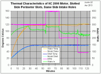
So here are the test results on the machined side cover plates with NO additional blades or scoops of any kind installed. In these experiments, I changed the methodology a little to get more data per individual test run. The hub started off at room temp and was spun at 300 RPM with 40A of peak to peak phase current until the CA's thermal rollback kicked in and the temperatures stabilized. Once steady state was achieved, then the dyno speed was changed to 400 RPM until things stabilized again, then reduced to 200 RPM, and finally to 100 RPM. Here's an example of what the resulting data looks like:
Multi RPM Test Example.gif
The reason that the temperature of the stator settled to slightly different values is just because the CA is doing a linear temperature rollback without integral feedback. At lower RPM's the battery current needed to maintain the 40A of phase current was less, and less amps means that the CA is at a higher temperature point on the rollback curve.

With the steady state data it is straightforward to calculate the effective thermal conductivity from the stator to ambient, which will be the basic metric by which I'll be comparing the effectiveness of different cooling approaches. For instance, at 200 RPM you can see that the average input power to the hub is ~230 watts, while the stator temp is at 118 degrees or about 98 above ambient. The approximate heat conductivity is therefor 230 watts / 98 degrees = 2.35 watts/degree.

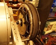
This test was done first with the machined perimeter slots,
a) With intake holes both on the left and right sides taped up.
b) Second, with the intake holes opened on the same side as the perimeter slots
c) Third, with the holes on the opposite side plate opened up while those intake holes on the machined plate were covered again.
Slotted Perimeter on Dyno.jpg

After that, I swapped the side cover for the one that had the 30 smaller 1/2" holes around the perimeter, with the thought that it might provide more of a 'fan blade' effect, and repeated just the 'c' experiment with center holes on the opposite side cover open.
View attachment 1

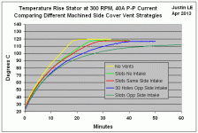
Here is how the stator temperatures looked in all these experiments, along with the reference setup with no vents in either side plate:
Machined Side Cover Temp Rise.gif
You can see that the addition of the milled perimeter slots with no "intake" holes had a measurable effect on how long it took the motor to hit thermal rollback, increasing from 19 minutes to 26 minutes. Opening up the intake holes on the same side as the machined slots had only a very marginal improvement over no intake holes. However, opening up the holes on the opposite side cover instead had a huge effect. You can see that with the opposite side cover holes open, the motor never got hot enough to hit thermal rollback. This is a similar observation to the first set of tests with simple drilled holes in each side plate, where there effect of holes on both side covers was much more than twice the improvement you get from having them one just side plate.

The same setup using the 30 smaller holes rather than the 10 elongated slots performed good but not quite as well, still hitting the thermal rollback at the 40 minute mark.
 
Very impressive. Holes on both sides, it is!
 
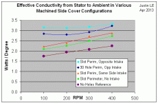
When the results for the calculated thermal conductivity compared over RPM for each test setup, this is what we get:
Rtot versus RPM machined side plates.gif

The effect of slots/holes on both side covers is fairly pronounced, and with the long perimeter slots the heat flow at low RPM's is increased about 80% over having no holes, from 1.75 to 3.15 watts/degree. Because of the I^2R relationship to power, that means that the vented motor could sustain SQRT(3.15/1.75) = 1.34 or 34% more continous torque output than the sealed hub.

Interestingly, in the situations of holes just one one side plate, or no holes at all, the thermal conductivity shows a fairly linear increase with RPM. However, in both experiments where I had the holes open on both side covers, the curve shows a decrease in conductivity from 100 to 200 RPM, and then it increases again. I suspect a lot of this might have to do with the particular nature air flow caused by the fan, which has a fairly convoluted pattern flowing around and through the dyno bench, and with the motor spinning who knows what kind of flow pattern results.

-Justin
 
Great work Justin. Improved cooling but I seems like flow and the coefficient of convective heat transfer from the stator are still quite low. Since airflow rate is going to be difficult to quantify, how about turning the fan off and getting a subjective feel for the amount of flow coming out of the exhaust holes and how warm the air is toward the end of a good run? Based on the limited change in cover temps I think we're still at cases of low flow, unless I'm not giving adequate consideration to the effect of time. To me a 60° shell at only 1300W power input doesn't support the case I've speculated about of flow following path of least resistance along the side covers and largely bypassing interaction with the hot stator.

It's getting more and more interesting, though the variables are starting to get so numerous that subjective analysis will be beneficial.

Blades should put significantly more meat on the bone, since ventilation is looking pretty lean so far. To me it's funny how people think it's time to conclude anything, because I think the stator is still too hot. You definitely have some hard fought valuable data. I just wish I was in easy driving distance, so I could come help.

John
 
Blades should put significantly more meat on the bone

Good point John. I am wondering also how much air drag we are adding with the venting and internal fan options. The more air we are messing with the more energy we are dissipating for the added cooling. At some point we may oppose beneficial effects.
 
Even though it is not likely going to be better it might be interesting to open up the intake holes on both covers..with one side exhaust.


If that looks promising you could try two sided intakes, and two sided exhaust (I know you don't have matching side covers though)

With inner intake and outter exhaust on the same side you only have flow across one face of the windings

With inner intake holes on one side and outter exhaust on the other the flow would be diagonal

With inner intake holes on both sides and outter intake holes on both sides there will be a cross flow

Also maybe outter intake holes on one side and outter exhaust holes on the other for direct flow across the windings (no inner holes at all). In that case the intake and exhaust holes would acutally be both and the flow would be both ways which ever way the wind blows. Should not be better but it would be good data
 
Is it me or are those slots massive? They seem bigger than any one else's I've seen. And I personally wouldn't dare ride the way I do (jumps) with what little support it looks like is left.

Since there's so much debate about the size of the holes, (and this thread will be "Definitive" :mrgreen: ), it'd be great to see data for the small holes/slots too.

If you have 30 1/2" holes, what's the total area of the slots?

I am absolutely loving this thread!
 
John in CR said:
how about turning the fan off and getting a subjective feel for the amount of flow coming out of the exhaust holes and how warm the air is toward the end of a good run?

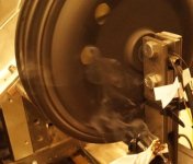
As you suspect, it's really not much. By hand the air turbulence around the spinning motor doesn't feel any different from having no openings in the side plate, and with the 'smoke test' approach there is no no clear path of any suction effect in and out of the holes. The smoke just wafts around:
Smoke Test.jpg

Blades should put significantly more meat on the bone, since ventilation is looking pretty lean so far.

Yup. This is what we have prepared for next in line:
Radial Blades.jpg

As shown, the blades are oriented radially which would be direction neutral, and would make sense as part of the structural ribs of a custom made side cover where the direction of rotation in the final motor isn't necessarily known. However, give each blade a little twist:
View attachment 2

And presto, we can re-orient them them all in a spiral pattern much like a squirrel cage fan, which should do a better job of pulling the air from the center and pushing it to the periphery.
Sprial Blades.jpg
I haven't put it on the motor itself yet, but we had it spinning on the lathe at 350rpm and it would suck a stream of smoke from about 4-5" away in a straight horizontal line to the middle and then whip it out through the holes.

To me it's funny how people think it's time to conclude anything, because I think the stator is still too hot.
Well not just that, I've still just been collecting the basic benchmark data. The real fun with blades, fans, liquid heat transfer etc. is only just beginning!

-Justin
 
speedmd said:
Move the air fully across the magnets from low on one side to outer on the other side!

I'm not really sure if low and outer holes makes any real different, I think it has to do more just with the presence of holes on each side which allows external air pressure differentials (from fan, slight side breeze etc) to generally move air through the hub. I got the same effect when both the left and right holes were at the same location in the side plate.
I missed if you were increasing fan/ air speed with the rpm.
Nope, the fan is on max all the time, and even though it feels like a huge breeze, when measured it is at most 12 kph on the right side of the motor, and on the on the left side where there is more interference from the dyno machine etc. it ranges downwards quite a bit with some areas especially near the bottom of the motor that are clear dead zones with no flow at all. The effect of external air flow (speed and direction) on the cooling ability of the hubs is sure to be quite large, although more difficult to quantify without like a windtunnel or something.
Interesting that the smaller perimeter holes come closer to the big cutouts at high rpm. :?
Yeah, I'd like to be able to put error bars on all the data in order to help us see whether observations like this are significant or if they fall within margin of uncertainty, so I wouldn't draw too much conclusion just from this one datapoint.

-Justin
 
Justin,
I understand the difficulty in accurately determining wind speed (past a moving/spinning motor), particularly when a rider is blocking some of the air. Even if the bike is moving 30mph, the wind speed past the motor is anyones guess. However, maybe you could strap your anemometer to various places on your moving bike. Then compare your "bike speed" against your "wind past motor" speed. This may give us a better feel for what a 12kph wind speed (in a lab setting) is in a real life setting.

Adam
 
Back
Top