Definitive Tests on the Heating and Cooling of Hub Motors

justin_le said:
To me it's funny how people think it's time to conclude anything, because I think the stator is still too hot.
Well not just that, I've still just been collecting the basic benchmark data. The real fun with blades, fans, liquid heat transfer etc. is only just beginning!

-Justin

Great work, Justin.

About early conclusions: this really shows how little is known even about baseline dynamics. In science, we are allowed to conclude anything that brings us further in a reasonable way. To me, this is the perfect science experiment, because the next actions are really based on the previous results, even though there is a clear overall method.

What I mean is that at this time, it would really be useless to do any experiments with blades but without holes. Even though we knew beforehand that it would be non-sensible to do so, the data shows it is actually unlikely to provide better cooling than using blades with vented covers. Therefore, the conclusion is not to continue with unvented covers, and that intake and outlet on opposite sides makes the most diference. And this is what we will build upon with the next experiments, blades, fans, liquid heat transfer, waterspray, whatever. What is wrong with making this conclusion?
 
My thought on blades is not only to spin the air for more volume of flow, but to also push air away from the side covers at the stator, ie not perpendicular to the covers. I did mine that way from the beginning, but previous results el Steak had reinforced my view. When he glued in larger vanes perpendicular to the side covers, he saw no temperature improvement of the stator over his standard test route. His 9C covers had small vanes, so I figured the larger vanes must increase flow. The only reasonable explanation I could come up with was that the increased flow must bypass the stator without doing much work. That simply can't happen on any motor I've vented, and every part of the end windings get a small puff of air from each passing blade on each revolution. Individually they may not be much, but 4000-5000 small puffs of air on the end windings every minute before the flow moves to exhaust must add up.

I try to make them act like both radial and axial blades, and I worry that blades perpendicular to the sides act only like radial blades.

I like the adjustable angle rig. My understanding is that straight radial will push more volume, and while angled rearward reduces flow it can pull more pressure. Ours may not pull enough pressure to make much difference, but I always feel mine are compromised by intake restriction, so I angle them in that manner.

John
 
Justin

This may be a good time to stop and discuss / rethink the nest steps that can help answer which direction to put your limited time / test resources toward.

Group has brought in some very good ideas and questions but to test of all variables one at a time, the experiment quickly out grows time resources. Further, without some mathematical weighting of response we will still not be able to make sense of control variables that may work together/ against each other. Doing this one variable at a time is not the way to go and certainly not any longer. You proved there is pay dirt. Now comes time to rake in the gold as efficiently as possible.

Here is how to do it. You want to set up the variable and levels in a fractional factorial and run a (partial) "statistically significant" number of runs of the experiment. Depending on how many variables you want to mess with at a time the experiment will grow in runs and breath of analysis. I have done this many times and can hopefully help a bit here. You then do the regressions and the results come out graded.

You can read some about the guy that helped put it on the map. http://en.wikipedia.org/wiki/Taguchi_methods
What is cool about using these methods is that you can calculate signal to noise of the various responses and know if your hitting/ missing the big factors effecting the responses in very short order. What Genichi told me is that this type of experiment, where you are finding the significant variables and mathematically analyzing/ grading them, his words were, "it's child's play". At least that is what I remember given the years and his broken English. His meaning I understood later are most powerful when directed at the design side of the problems and analyse variables against a loss factor. I think he won a Deming prize for that part. Here, he would certainly have us want to concentrate on making a motor that generated less heat to shed.

We need to look first at the responses and see if we should be looking at this any differently. The watt/degree may be suitable. He suggested several times in these situations we focus on minimize or in this situation maximize heat energy loss. Should I go on.
 

Uploaded with ImageShack.us

Thought this might be of interest. It would increase the pressure differential by both decreasing pressure further around tdc, and increasing it around bdc. Seems like a win win for venturi driven ventilation.

I wonder how to match it side by side. You could reverse the cowls to create a cross flow design. The design would be much better through the upper arc of travel, so I would look there for frame mounted fan integration. It depends where you draw the line
 
Lovin' it! Now put a dust cover to prevent debris from entering. Wow, 2 stroke mentality FTW! :lol:
 
Justin,
It seems like the "R1" value you are interested in is effected mainly by how much metal is left blocking radiation of heat from the windings. Thoughts?
Btw friendly1uk, you could have mentioned I moded the vented hub above.
EDIT:
just looked at the graphs again. and its obvous to me now that the perimiter slots and oposite side intake is the dominant heat transfer method, obviously this isnt just radiation from the coils through the holes, there must be a slight turbine efect and or venturi effect flowing air through the stator. I think this may be the new normal way to vent a hub.. we'll see as 2013 pans out.
 
Fan-tastic job on adding blades my friend!

Remember with a squirrel-cage, you want ejection tip angles aimed in the counter intuitive manner with respect to leading into the discharge. :)

Think a setup of fins designed well could at worst case double airflow through the center.
 
Lets look at the variables we are looking to adjust and set levels for. We can change and adjust these things to improve cooling, produce more power from the same motor or ideally make the smallest lightest most efficient motor with little worry that it will ever burn up without fair warning.

We call this making a robust design. We look also at the variables that we can not vary/control in real life and analyse the factors we can control to minimize the effects of the uncontrollable factors/variables on the responses.

With vent hole shape, we see some improved response with the larger slotted holes at the lower rpms. This may be a factor in the motors sustainability to be driven hard slowly up a hill. Possibly, we can vary the room fan speed also and see if this follows suit with a simulated lower ground / wind speed. Keep that thought.

We now have in addition to the vent holes and all their iterations, internal fan blades. We have to vary their size, quantity, one side / both sides, the angle (radial, plus / minus degrees) as well as their placement. Oh shit batman! This is where you test man jumps off the roof.

Some can assume more air will make better cooling and try to maximize that. Fair assumption, but, without weighing/grading each against the response, we may be better off with creating more internal turbulence via diverters /deflectors than trying to blow more air freely through the motor. Hard to tell without a suitable measurable response and crunching the numbers. Having said that, I can say with some confidence that we should not be making broad assumptions at this point. I have been burned way to many times doing that. Better to let the numbers do the directing. IMO It is time to get on board and set up a DOE (design of experiment) at least if you want to find the cheese, quickly.
 
Some more reading on modern DOE.

One of the great engineers of our time. Full of amazing stories.
http://en.wikipedia.org/wiki/Genichi_Taguchi

some basics
http://en.wikipedia.org/wiki/Fractional_factorial_design

http://www.me.mtu.edu/~jwsuther/doe2005/notes/doe_ch12.pdf

output looks like
1-s2.0-S002554081100643X-gr2.jpg


setup for a L9 experiment (4 variables, 3 levels each) Only nine runs.
1560110503009.png
 
friendly1uk said:

Uploaded with ImageShack.us

Thought this might be of interest. It would increase the pressure differential by both decreasing pressure further around tdc, and increasing it around bdc. Seems like a win win for venturi driven ventilation.

I wonder how to match it side by side. You could reverse the cowls to create a cross flow design. The design would be much better through the upper arc of travel, so I would look there for frame mounted fan integration. It depends where you draw the line

Here is the image again, showing the cowls in context of the machined hub from pendragon8000:

Uploaded with ImageShack.us

Here is my reply
http://www.streetstufffibre.co.za/Gallery.asp?VarMake=BONNET%20SCOOPS
 
There are lots of good ideas here, but I fear that since a hub motor that's mounted on the rear wheel suffers from being placed in the turbulence of the wind that has to flow around the riders legs (not yet modeled in the tests), any dependence on airflow past the motor will have less-than-optimum limits.

I remain convinced that the front disc brake of a car is a well-engineered part that has air-flow capabilities that are well-understood, and a motor-fan based on them will eventually prove to be an excellent performer. A vital part of this style fans' optimum performance is that the outer section is a solid disc. Car alternator fans that do not have a solid cap are made that way for cost-savings.

Here is a pic of bluefangs non-hub and external fan, and how I envision the optimum airflow hole locations:

BlufangMM.jpg
 
pendragon8000 said:
Justin,
It seems like the "R1" value you are interested in is effected mainly by how much metal is left blocking radiation of heat from the windings. Thoughts?

EDIT:
just looked at the graphs again. and its obvous to me now that the perimiter slots and oposite side intake is the dominant heat transfer method, obviously this isnt just radiation from the coils through the holes,

That's right. The data definitely doesn't support the idea that radiation heat from the stator to ambient via the holes is much of a player at all:

a) The first set of tests with plain vanilla holes had them located in a closer ID where the actual windings aren't visible at all, and that produced the same basic cooling effect as the perimeter holes.

b) With the machined side covers in the recent tests, I had two version. One with 10 elongated slots, the other with 30 smaller holes. The total open area in each case was pretty much the same, yet the few longer openings had a measurably better cooling effect. Radiative losses wouldn't differentiate between many small openings vs. few larger ones, just the total area to radiate from, while as others have pointed out with airflow is much greater with a few large holes than a large number of small ones, which is what we saw.

c) In a best case scenario where all of the stator sides are able to radiate directly to ambient with perfect emissivity, we'd have an effective radiating area of 2cm,*pi*18cm*2 = 220 cm^2 = 0.02m^2. With a roasting hot 120 degree stator, that's still just 5.67E-8 * 0.02 *(393^4 - 293^4) = 18 watts, or less than 10% of the heat input, so the gains to be had here are marginal.

liveforphysics said:
Fan-tastic job on adding blades my friend!

Unfortunately we didn't fully take into account the protrusion of the hall sensor wires over the windings, and so they ended up scraping those pretty bad. Blades are back in the shop for some additional trimming!
 
toolman2 said:
^that is all awesome :?
best thread ever.
and why are you called speedmd :?:

Thanks toolman2

Just hoping I can help Justin make some history here. Love cycling, and built a few dozen cromo road racing /mtb frames during the 80s and early 90s and caught the ebike bug while in china a few years back. Love the site and spending much to much time learning all I can on it. I build speed equipment now full time for Olympic skate racing hopefuls. For me the world these days is about speed. A jump from the engineering /quality control years I spent assuring medical and defense equipment, but much more fun and interesting. The md part is my initials but the nick name stuck many years ago.
 
Awesome Justin, I'm looking foward to the results of the fan tests!
Do you think the cast ribs in the side covers will play a role in upsetting the air flow ? It seems likely that it will create some sort of turbulance as they're right in the path of where the fins are directing air. Whether it's measurably significant is the question I suppose. And they do add to the structural support so I guess technically you'd want to weigh up hole size and placement elsewhere if you were going to grind them down, though it would be pretty trivial I imagine.

Friendly1uk, this is an awesome thread for the ages, don't clog it up with your petty crap.
If you're going to post a photo of someone elses work it's etiquite to mention the source, just as toolman did above when posting bluefangs image.
I see that you've only just joined here but surely this is universal knowledge (as is it not to show up and start fights)
 
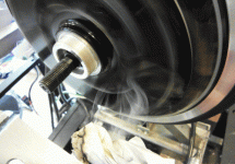
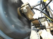
So it took a few attempts to whittle down the offending bits of blade that were scraping the hall wires, but it's running in the clear now.

With the blades oriented radially, motor spinning at about 400 RPM, there is fairly decisive air flow pattern going into the intake on the same side of the blades:
Smoke Test, Same Side Intake.gif

However, if the intake holes on the blade side are covered over, with only the holes on the opposite side plate available as intake, the resulting flow rate is not nearly as pronounced. There is some smoke going into the holes, but most wanders around:
Smoke Test, Opposite Side Intake.jpg
This could be in part because the internal 9C stator support is made from solid sheets of stamped steel with only six ~1" holes punched through them for air flow, as opposed to other hub designs that used a die cast spoked stator support that is much more open between the left and right halves.

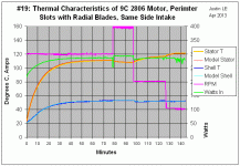
Here's what the experimental data looked like, starting at room temperature, running at 300rpm and 40A phase current until things leveled off, then going to 400rpm, 200 rpm, and 100 rpm until temperatures equalized at those speeds too:
Test19, Blades and same side intake.gif

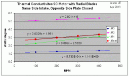
When the steady state temp data is used to compute the effective heat conductivities, (R1 = Stator->Shell, R2 = Shell->Ambient, R3 = Stator->Ambient), plus the net effective net conductivity, we get in all cases nice linear variation in thermal conductivity with RPM:
Lienar Resistances.gif

This differs from the previous tests with both left and right plates open and no blades where there was a distinct curvature in the Rnet vs RPM. Because all terms are straight line in this case, when a model is made using these conductivity coefficients with a linear RPM dependance, the results match up with the measured temperatures almost perfectly over the full 2hour test and the range of speeds. You can see that in the first graph above.

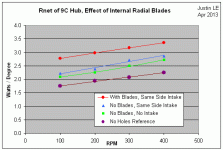
As for the comparison with previous results, the addition of blades seemed to add a fixed ~0.6 watts / degree over all speed ranges, compared to the same machined side cover with the same side intake and no blades
Rnet Graph with Blades.gif

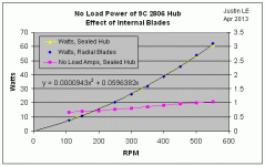
I didn't suspect that the extra drag caused by the blades moving air around amounted to very much, but just to be sure did an unloaded power test of the motor both with and without the blades. If there is any difference it is too small to be measurable:
Windage Comparison.gif

-Justin
 
Awesome stats Justin. So who's gonna be the first to sell us pre-drilled side covers with blades attached?

Would it make more sense to use plastic blades...to avoid any potential damage to the windings?

I've got intake and out-take holes drilled on one side cover of my HS3548...but still not sure from your data whether to drill both intake and out-take holes on the other side, or just out-take holes only.

Cheers
 
great work test bosses :D
so you have yet to do the radial blade other side intake, correct? I suspect this will sh!t on the same side intake from the previous test with machined holes. nice photo with the smoke.

NOTE: with the hub i machined/drill & filled , i did the smoke test with a chunk of inscence and it was a bit indicisive, there seemed to be a slight intake of smoke around the disc mount but the fact that its ribed like a turbine made the smoke blow around before it went in the intake holes. but i can say there was a nice little breeze coming out the vents. this verifies the turbine efect only of my desighn. venturi is another story.
Edit:
However, if the intake holes on the blade side are covered over, with only the holes on the opposite side plate available as intake, the resulting flow rate is not nearly as pronounced.
Sorry I must have misunderstood that before.
 
Great work Justin

Blades not causing much additional drag is a huge win win. Some experiment/ test housekeeping for you to ponder. When taking data points /measurements, it is always better to take them in pairs at a minimum. Even with digital indicators, you can note a high and low reading within a few seconds time and average the readings. This way you can get a average value that will always come closer to actual. With the temperature probe being in one spot on one side, we may get confounded results on the one side vs two side hole measurements. If at all possible, run two probes and average temp between them would help eliminate this issue. Critical systems would use three sensors and take the two that agree closest as valid and ignore the outlying one until it can be verified as real.

One data point will be a average now and carry much more weight with this approach. It also will add some mathematical significance (lower std deviation) when the readings are much closer to one another signifying less variability and possibly greater process capability . This may help prevent you from overlooking some pay dirt.
 
Great work Justin. With covers going down to what my hand calls warm and the times to reach max temp really stretching out to long periods, the results are likely comparable to my efforts. My higher rpm benefit is offset by smaller holes. The stator temps still surprise me, but the closest I've come to continuous is maybe 10 minutes of continuous uphill grade. The much higher power I run probably makes up for it, but with ventilated you get continuous cooling despite intermittent heat generation. The includes when stopped. eg Ride hard and stop at the store and feel the warm air rising out of the motor vents, but unlike for a sealed motor, you come back out and it's cooled way way down. Sealed motors stay hot for a very long time.

I look forward to seeing where you take it next. The 9C doesn't allow much width for blades, so fans are likely to do better. I'm partial to blowers like I use for draw air through controllers, something like these http://www.alibaba.com/product-gs/815553768/40mm_5v_mini_blower_fan.html. Pulling air through the stator spokes and blowing it radially seems perfect to me.

John
 
Hey Justin,

It's nagged at me a couple of days now, so I felt compelled to post. That is the lack of any power draw for the "fan" portion of your ventilated motor. Nothing is for free, so if it's not taking any more power then it can't be doing much real work inside the motor. On the vented motor I have the most experience running, we saw a .4A increase in no load current after ventilating, which is 30W. I'm sure our "fan" isn't the most efficient, but negligible fan drag tells me there's a lot more stirring of the air and forcing it at the end windings to be had on your version of venting, especially since you have much much more cross sectional area for your intake and exhaust for a much freer flow of air.

You're running a modest power limit, so even running continuous I'd like to see that stator temp stabilize below 100C. At 100C that stator should be able to transfer a whole lot more heat directly to the air flowing through, so the flow is too low and/or it's not getting enough contact with the stator.

John
 
John in CR said:
It's nagged at me a couple of days now, so I felt compelled to post. That is the lack of any power draw for the "fan" portion of your ventilated motor. Nothing is for free, so if it's not taking any more power then it can't be doing much real work inside the motor.

For sure! But it's exactly what I was expecting for such generally low speeds as a hub motor. I presume that the power to spin a fan goes at roughly the cube of the RPM? So what I saw as no more than a watt or two at 300 rpm could be more like 30 watts at 1000 RPM. How fast were you spinning the motor to get the 0.4A no load increase?

You're running a modest power limit, so even running continuous I'd like to see that stator temp stabilize below 100C. At 100C that stator should be able to transfer a whole lot more heat directly to the air flowing through, so the flow is too low and/or it's not getting enough contact with the stator.

The blades are basically as large as can be fit inside the motor casing without risk of scraping any wires, and the holes as has already been pointed out are already so large as to leave the thing structurally dubious. So my feeling is that there isn't a whole lot more gain possible via passive induced airflow from the direct drive motor RPM. I do think that openings and blades on both the left and right side cover plates would be the best, rather than trying to pull air 'through' from ones side to the other.

-Justin
 
Hi Justin,

Great to see some real emperical testing being carried out here. I'm presently running an oil heat transfer medium in my Crystalyte HS3540 and thought I would briefly share how effective I've found this method to be.
If I'm cruising on the flat at 34 to 36 kph (around 287 rpm with 26 inch wheel) the battery input power is around 600 watts. The motor power according to your simulator at this speed is around 480 watts. This means the approximate heat generated by the motor's windings (ignoring controller heat losses) is 120 watts. When I ran the bike with a standard HS3540 with no oil (or cooling holes), the motor windings would reach a somewhat variable steady state temp of approx 65 to 75oC. With the oil added, the same running conditions would result in a more stable steady state motor winding temp of around 42oC. This is with an ambient air temp of approx 20oC. So:

Without oil: Temp difference = 75 - 20 = 55oC. Heat dissipation = 120 watts. Therefore, total thermal conductivity = 120 / 55 = 2.18 watts / degree. Note: This is pretty much identical to the 9C motor (standard with no cooling holes).

With oil added: Temp difference = 42 - 20 = 22oC. Heat dissipation = 120 watts. Therefore, total thermal conductivity = 120 / 22 = 5.45 watts / degree.

Conclusion: Assuming I've worked all this out properly, the addition of oil as a heat transfer medium increased thermal conductivity by a factor of up to approx 2.5 times. So looking forward to seeing what results you come to with proper controlled experimentation. Would be great to see also, how much drag the oil adds to the motor. I personally haven't noticed much, but also haven't done any definitive testing.

cheers,
dave b

Edit: Please take the above calculations as rough ball park figures only. Taking readings on the fly with undulating roads, constantly changing headwinds, and trying not to run into anything in the meantime etc, coupled with considerably long time periods for motor temps to equalise, makes accurate data collection problematic.
 
Back
Top