Gyro for controlled Wheelies

I'm afraid you've lost me.

An accelerometer measures tilt with reference to gravitational acceleration, so is unaffected by the slope of the ground. If you're on an upward hill and the bike is at 10 degrees to horizontal, that's just 10 degrees of your maximum tilt allowance you've already used up. I'm not sure why you'd need/want to know the bike's position in three axes, unless the system will also stop the bike falling over sideways? :D

That's what got me thinking about using the y-axis to measure the tilt (wheelie) of the bike, with the z-axis subtracted to stop the forward acceleration of the bike influencing your tilt measurement.

Or have I missed the point?
 
I don't see why it needs to be so complicated :mrgreen: all you need is proportional tilt switch that can be turned on and off from a switch on the bars..

and just mix the tilt switch signal with the throttle signal... easy peasy :D same sort of setup what they use on gas motorcycles for teaching peeps to wheelie
 
gwhy! said:
I don't see why it needs to be so complicated :mrgreen: all you need is proportional tilt switch that can be turned on and off from a switch on the bars..

and just mix the tilt switch signal with the throttle signal... easy peasy :D same sort of setup what they use on gas motorcycles for teaching peeps to wheelie

The problem I see with using acc sensors and gyros is that it will make the whole system very difficult to process as on a bike you will also have to monitor CG for it all to work really well and this can become a major headache.. lets face it it will depend whether you want a control system to enable you to learn how to do wheelies or a control system do wheelies automatically.. forget trying to do walking pace wheelies if the bike has a freewheel fitted this will be near on impossible without also monitoring the cg ( even a segway can throw you off in certain circumstances ( don't ask me how i know :oops: )) and the CG only moves a few degrees so imagine how much more its going to be on a bike. brute force ( 10+mph ) wheelies are pretty easy anyway as long as you have extra power on tap, reasonable throttle control and don't change your body position to much. Controlled wheelies on a motorcycle also needs the use of the rear brake so this is where the whole thing may become unstuck.
 
Enough balls and skills does replace the need of a front wheel.

[youtube]WKW39MY_pPo[/youtube]


There is a chip for doing "dead reckoning" that has a bunch of gyro's on various axis and magnetic field sensors, they allegedly can keep a correct idea of horizontal even in bumpy situations.
 
cant do this without a rear brake.. and very good clutch/throttle control... :D
[youtube]Nfp2f53OH3g [/youtube]
 
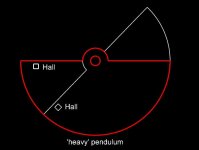
...what about something very simple - a mechanical device using hall sensors....one fixed side, one side is a swinging pendulum... the pendulum will always remain horizontal, and will cut back - or cut throttle when it gets critical.

pendulum.jpg
 
Willow said:
...what about something very simple - a mechanical device using hall sensors....one fixed side, one side is a swinging pendulum... the pendulum will always remain horizontal, and will cut back - or cut throttle when it gets critical.


What happens when you hit bumps and things that send the disk slamming around? This is the same typical problem gyro's run into, the moment they encounter anything out or range or beyond sensitivity rates, they have lost tracking of 'horizontal'.

If you want a device like that to work, you can do what older aircraft did and put it in a 3-4 axis gimble cage with a motor spinning a weight at high speeds, but even those flip out and just tumble when you hit a big enough bump.
 
This is an example of a dead-reckoning chip. It uses a bunch of very fast very precise gyro's (including all yaw axi) and wheel speed sensors and whatever other data it can get.

http://www.u-blox.com/images/downloads/Product_Docs/u-blox_3D_Dead_Reckoning_for_Vehicle_Applications.pdf

A chip like this, mounted somewhere close to the bikes COG should enable automatic wheelie control.
 
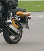
Wheelie school setup,,, very simple...
wheelie_school.jpg

The hall pendulum will also work ( you only need 1 hall sensor and 1 magnet ) but like LFP has said it may move around to much and not take into account bumps . But as it will proportional even this may not be so much of a problem as long as the pendulum can move fast enough,is short and has some resistance in swinging.
 
Punx0r said:
The pendulum will also swing on level forward acceleration

but that will not be such a bad thing.. will it :?: .. depends how loose it is to how it effects acceleration.
 
This is the basics of how you control an inverted pendulum. I've been working on control theory a lot so this actually isn't that difficult if you can do the math, you must be able to do math if you want to control stuff with electronics with loops.

PID control is well suited to this task, bang bang control not so much
http://ctms.engin.umich.edu/CTMS/index.php?example=InvertedPendulum&section=SystemModeling

The same type of system could also be applied to gas bikes. I was thinking a wheelie system would be nice and could be dialed up or down so that one can train on how to balance without flipping backwards.

Personally I've never been able to get the feel for a balance point of a controlled wheelie unless you count a wheel chair.
 
One solution is not much different than how these things work, right?
http://openschemes.com/2014/10/30/airwheel-x3-teardown/
 
Megabyke said:
One solution is not much different than how these things work, right?
http://openschemes.com/2014/10/30/airwheel-x3-teardown/

What solution? It's just a tear down of an inverted pendulum device.

In order to properly do this (auto wheelie), math, physics and control theory will be required.

The other option would be to make a bang bang type controller which could be tuned by the end user. Just have a settable angle to prevent flipping and when that angle is reached, cut the throttle. The back off throttle rate could be adjusted as well, but we are talking all open loop. This means the entire system could be over loaded by a change in center of gravity, how quickly the front end comes up, etc. There are ways to compensate for this, but it starts to get tricky. It's much cleaner to solve the issue using physics and control theory. The difference between an open loop helper and a PID loop tuned auto wheelie controller would be huge. The physics/control theory based controller is actually easier to design than the open loop model...if... you know how to do the math. I've been at control theory for about 2 months now and I'm just starting to understand it (the math is hard but awesome). It's astonishing the doors it opens for an electrical engineer that understands physics and mechanical engineering.

I've got some totally crazy kinetic art ideas I'd like to design. Kinda funny that after spending so much time learning all this making bad ass art is way up there on my list. There is art in math, sometimes people just need a little help to see it.
 
zombiess said:
Megabyke said:
One solution is not much different than how these things work, right?
http://openschemes.com/2014/10/30/airwheel-x3-teardown/

What solution? It's just a tear down of an inverted pendulum device.

In order to properly do this (auto wheelie), math, physics and control theory will be required.
...
It's astonishing the doors it opens for an electrical engineer that understands physics and mechanical engineering.

Agreed! I have wanted to do this for a while and was indicating that there are already a lot of machines designed to maintain a balance point on one wheel and accelerate/decelerate while doing such. (segways, solowheels, SBU, ryno, homebuilt electric unicycles, etc.) I am waiting on delivery of my self balancing unicycle to see how well they work, but the tear down link I posted was to show that it can be done cheaply with minimal hardware using a single gyro and low end microprocessor integrated into the controller. An MIT student has laid out his DIY self balancing unicycle solution clearly for us using an arduino which is a heck of a lot easier than trying to hack one of these chinese devices. As much fun as I had cutting my microcontroller teeth back in the 90's programming simple robots with the Motorolla 68HC11 in assembly, I am inclined to follow his foot steps and opt for the modern high-level programming simplicity of the arduino. :wink:

I am sure we agree that the main challenge is designing a system that can safely get the front wheel from the ground to the balance point if the rider has zero skill and at higher speeds than 10mph since that seems to be the limit of the current generation of code/cpu/gyro sensitivity and sampling rate for pretty much all of these machines. It also should be noted that all of the unicycle variations still require considerable acquired rider skill and implementing this on a bike would certainly be the same.

Some great source code to get jump started: https://gist.github.com/boyers/2475495

My plan:

1. Get an arduino with an ATmega328P and $6 gyro: http://www.amazon.com/Kootek-Arduino-MPU-6050-gyroscope-accelerometer/dp/B008BOPN40
2. Wire it to override the throttle and activate regen for HT3540 DD motor via a push button switch (my commuter has quite a large battery on the rear rack which will make it much easier to find the balance point)
3. Find someone talented/crazy enough to be the test pilot and gear up for the crashes
4. Pop a wheelie close to the balance point and hit the button
5. See what happens
...
N. Extend the code to make it automagically lift the front to the balance point and maintain a preprogrammed speed when the button is pushed

It is a lot easier said than done, but I am crazy enough to consider giving it a shot after the holidays if no one else wants to be the guinea pig. I have the riding and technical skills/experience to attempt it, just not the time!
 
zombiess said:
In order to properly do this (auto wheelie), math, physics and control theory will be required.

The other option would be to make a bang bang type controller which could be tuned by the end user. Just have a settable angle to prevent flipping and when that angle is reached, cut the throttle. The back off throttle rate could be adjusted as well, but we are talking all open loop.

If you had a pendulum arrangement like willow posted it will not be open loop , you will have a linear hall sensor so as the mag approaches the sensor the voltage goes up and as the mag moves away the voltage will go down .. in simple terms this is subtracted from the throttle voltage.
 
gwhy! said:
zombiess said:
In order to properly do this (auto wheelie), math, physics and control theory will be required.

The other option would be to make a bang bang type controller which could be tuned by the end user. Just have a settable angle to prevent flipping and when that angle is reached, cut the throttle. The back off throttle rate could be adjusted as well, but we are talking all open loop.

If you had a pendulum arrangement like willow posted it will not be open loop , you will have a linear hall sensor so as the mag approaches the sensor the voltage goes up and as the mag moves away the voltage will go down .. in simple terms this is subtracted from the throttle voltage.

Yes that's true it is feed back (bang bang type), but hard to dial in. How would you determine the amount of throttle subtracted or added which is required to maintain a set position? What about filtering out noise and oscillations in the sensor setup? If you can ride a wheelie because you have the skills, your brain does the math and your hands/feet and body make necessary adjustments to maintain the balance and stop oscilations. If you want an electronic device with sensors to do it; it has to understand how all of this works, the desired angle to be maintained and handle any disturbances that upset the balance, dampen oscillations caused by overshoot, etc.

Lets take the hall sensor arrangement and pull the front end up really fast. The hall sensors start cutting the throttle, but how much throttle and how quickly? Will the throttle act fast enough? If not, then you flip over, too slow and the front end might come crashing back down. Both of these conditions are overshooting the desired result, a controlled balance point.

Another question is do you want to power wheelie under control or just get to the balance point and hold it there?

To better understand what is required it would be a good idea to draw a free body diagram of the forces involved in "doing a wheelie". From that, the math that describes the physics can be found and translated into transfer functions. Those transfer functions can then be placed into a control loop (probably PID) to maintain a set angle/speed, etc. Add in a speed sensor and now you can program the bike to do a controlled launch that just hovers the front wheel a 0 to x centimeters above the ground and as speed increases it could automatically bring the front down gently or it could wait and let that happen naturally.

I'm not saying this is the only way to do this, but it's most likely the best way and it is how I would do it because it opens up all kinds of options for cool features.

This is a very cool project and one I wish I was able to take on the challenge of, but I'm way too busy :( Back when I thought about trying to do this earlier this year I had no idea just how difficult of a challenge it was. Someone should give it a shot, even a simple anti flip device to help people learn to wheelie themselves.
 
still cant see why you would call it bangbang style , its a closed loop that controls proportionally. You can put the output of the hall sensor into a pid if you wish ( this will improve control if it can be tuned in ) yes you will have to set it up, but the more i think about it i think it can work reasonably well as long as the mechanical side was sound.
 
gwhy! said:
If you had a pendulum arrangement...

You will have a random bouncing indicator of nothing useful.
 
liveforphysics said:
gwhy! said:
If you had a pendulum arrangement...

You will have a random bouncing indicator of nothing useful.

im not talking about a magnet on a piece of string :D , but something a lot more precise and a lot more weight to it, maybe a 4-5cm diameter disc, I'm not saying that it will work, but i think it could work

edit: or you could just buy a tilt sensor :mrgreen:
 
Back
Top