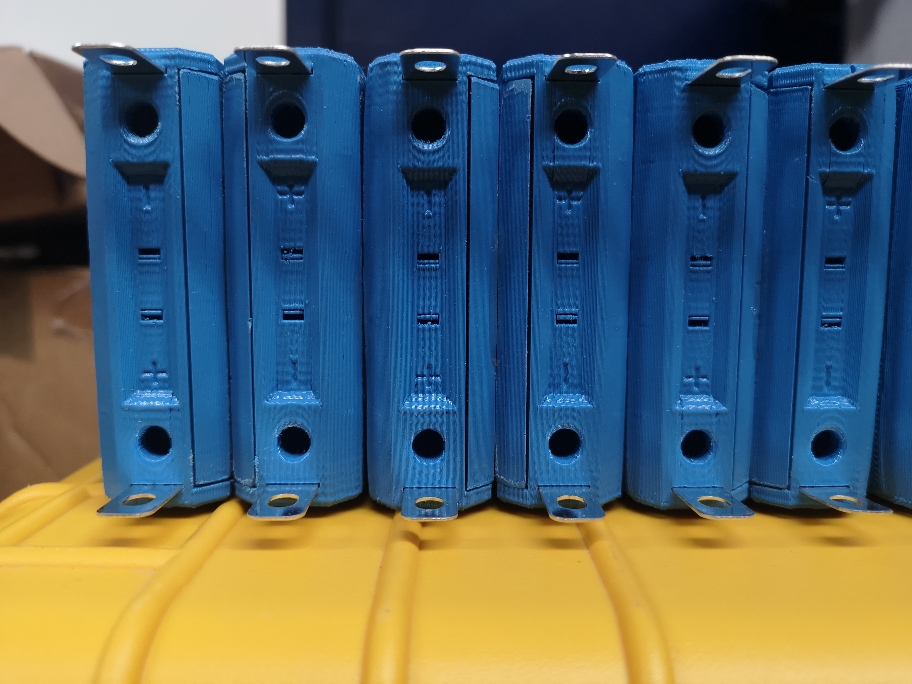
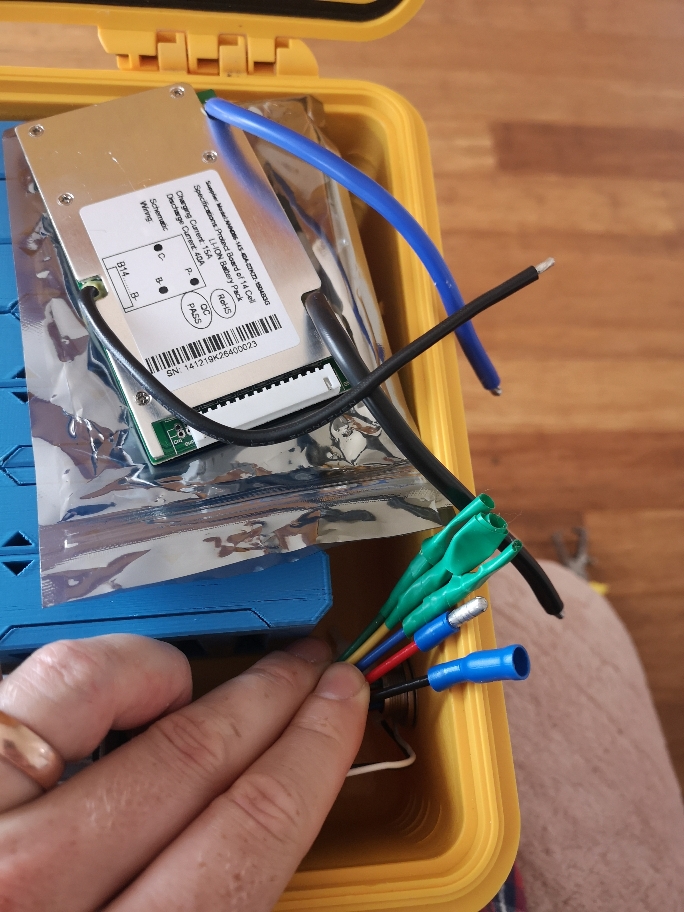
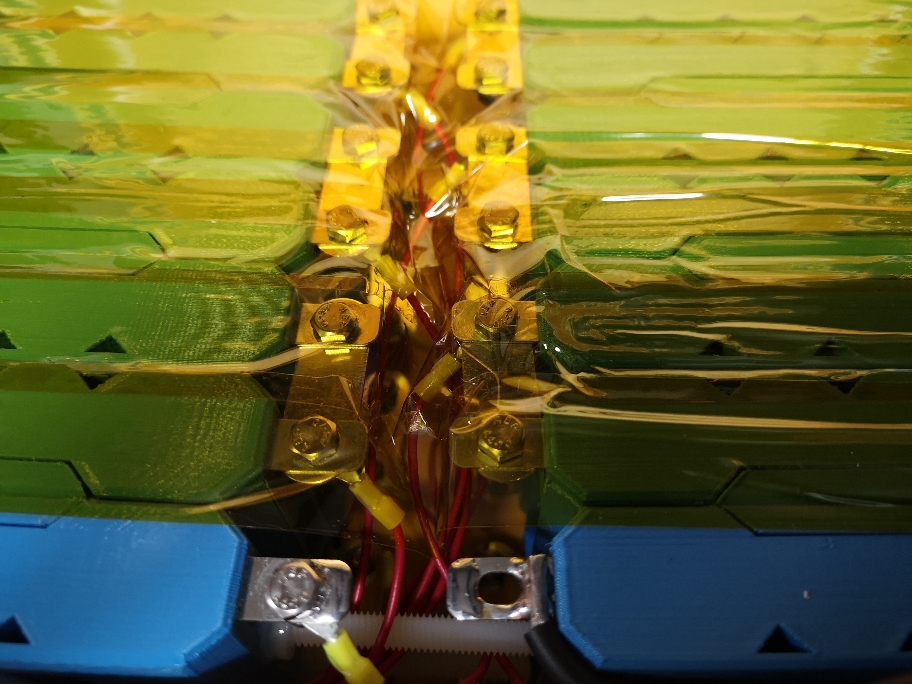
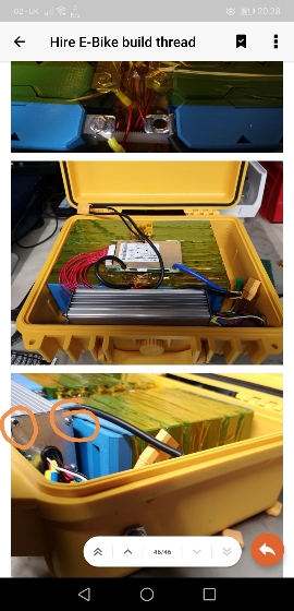
Battery is finally all connected.
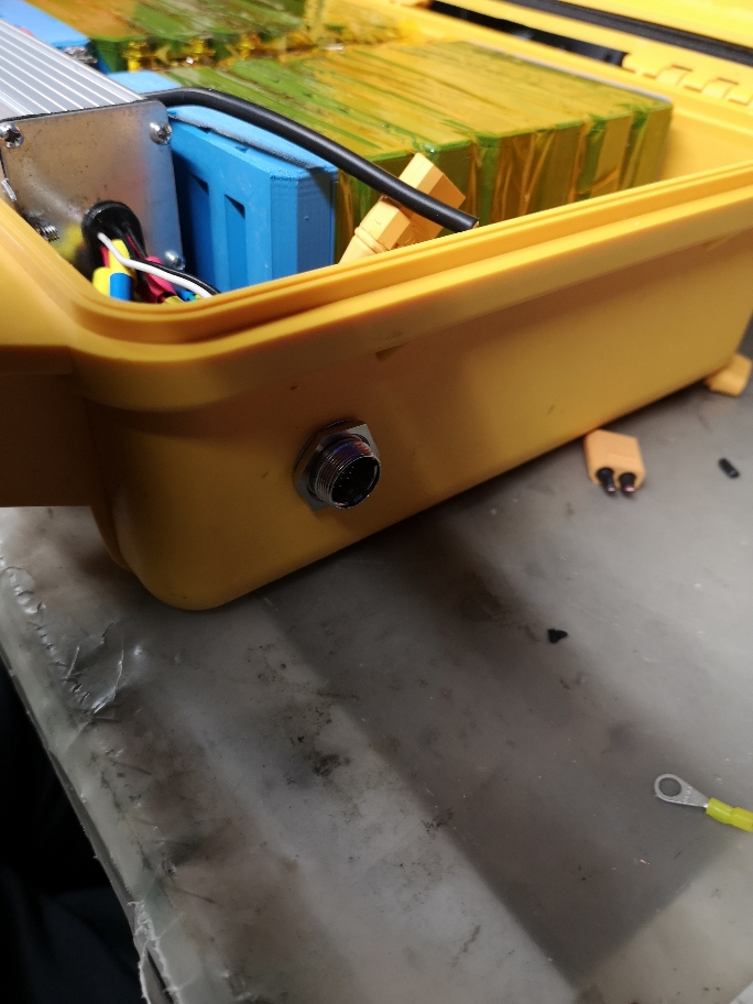
Controller is all wired up to a multipin connector on the side.
Undecided what I'm going to do with the 3 motor wires. Probably XT90 connectors as I have a bunch of them.
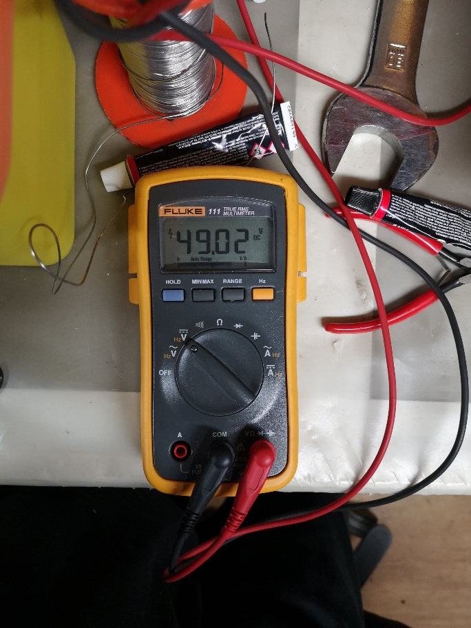
Only showing 49v though. So cells are at 3.5v and ready for a charge. Case is weighty but not as heavy as I thought it would be.
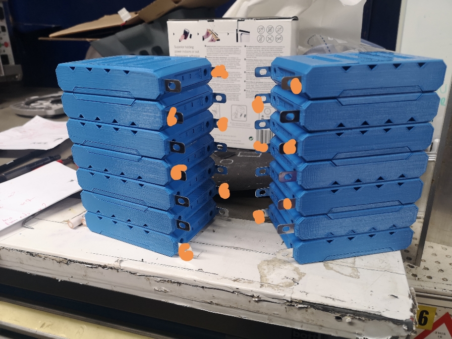
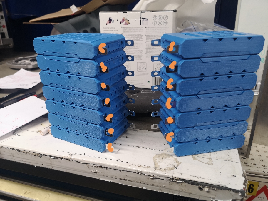
Also run kapton tape in between both battery blocks and nylon screw in between to prevent both sides touching.
What I've learnt from this so far...
Shit I need to plan more. Like lots more. Ran into so many niggly little issues that could of been avoided.
I need to have a clearer workspace. It was carnage in my workshop. So many things in the way, piled on top of each other. Soldering iron next to batteries, next to tools, with scraps lieing around. Not ideal.
I need to focus on one idea, complete, then move on. This will be helped with a more detailed plan.
Next up is the handlebars and all the electrical connections from brakes, throttle, etc. They all need to be wired into the multipin.
Sent from my CLT-L09 using Tapatalk


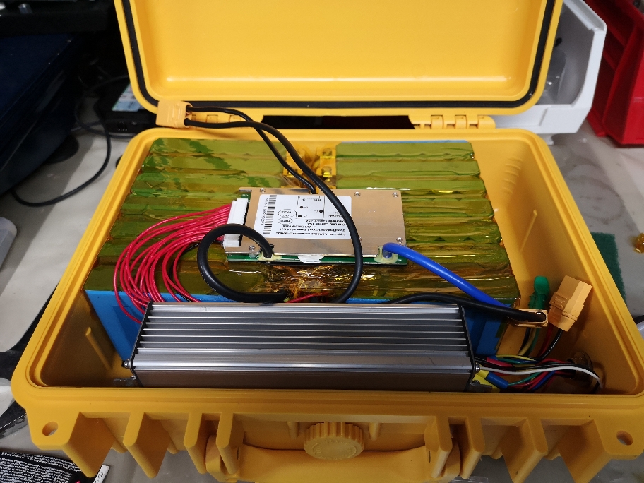
") I was going to say, that's going to be a toasty pelican case, but I just saw that you plan to leave it cracked open.
I was going to say, that's going to be a toasty pelican case, but I just saw that you plan to leave it cracked open.