If you mean that you'll:
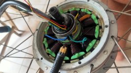
--remove the internal controller (or at least disconnect it from everything) and use an external controller
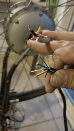
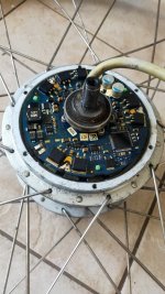
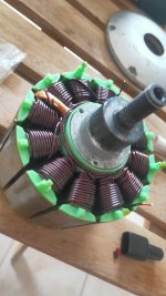
--replace the existing wire harness thru the axle with a new one that has at least the three appropriately-thick phase wires, wired inside the motor to the three phase connections for the windings
then if your external controller is sensorless-capable, then yes, it will work with just the three thick phase wires.
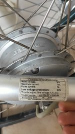
If your external controller is not sensorless-capable, you'll also need to have the usual five wires to the usual three hall sensors inside the motor, for 5v, ground, and signal on each one. If it doesn't have built in halls you'd have to install them in the correct spacing in the motor, or build a suitable external encoder (like Burtie did with an optical system) that still generates the right signals.
You can take a peek at my
Stromer Mountain 33 Motor & LCD -- Repair / Hacking for how I went about gutting an internal controller and wiring such a motor with an external controller. (I then used that on the SB Cruiser for a few years before I finally broke the axle a few months back). Or there's GCinDC's Hacking a couple Stromers thread, and Doctorbass I think has a thread for a bionx motor gutting?


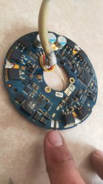
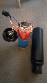
 hopefully the nice new Sanyo cells are ok. Anyone know who could replace the BMS for me here in Australia?