jonescg's cylindrical cell build thread

[youtube]jumFyhtjylM[/youtube]

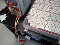
The battery is coming together slowly. This seems to work satisfactorily. But a bigger welder with more instant amps would be ideal. The sheet metal welders only vary the energy by increasing the time it stays on for, which gives the material ample time to soak away the heat. I need more capacitors!
20210117_200817.jpg
20210117_155156.jpg

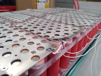
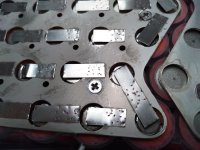
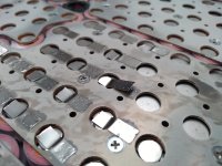
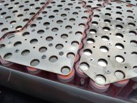
The reason I'm using countersunk screws is to make sure the thermal path from the ends of the cells to the face of the battery module is as short as possible.
 
Chris - do I understand correctly that you'd like to use nickel to connect from the top of the cells to the busbar?

Have you tried a "split" piece of nickel or the "slit" technique?
 
Yes I have tried the equivalent by placing one electrode on the busplate and one on the nickel strip. Makes no difference to the quality of the weld.
 
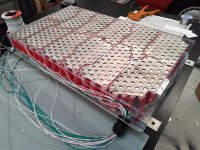
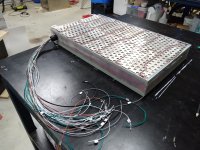
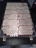
A little progress today - BMS wiring starts to go in. Odd numbered cells first. Then flip, even numbered cells. Then glue the sides on and let that set, then finally spot weld all the cell tabs.
20210118_163001.jpg
20210118_162939.jpg
Hopefully by then my thermal epoxy adhesive will arrive...
 
If you weren’t literally half way around the world I’d loan you my 800 watt second CD welder.

I think it would make short work of your project.

Tom
 
Last year I found a video where one guy welded together two aluminium with a little trick (put two thin steel on each side) :)
https://www.youtube.com/watch?v=gcgC3V3mkcw
But it required to access both sides you can not do anymore :(
 
I actually tried that with exactly the same spot welder - gravity was enough to unstick it :cry:
 
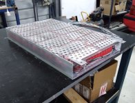
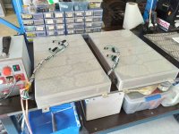
Second module ready for spot-welding.
2nd modole built.jpg
2 modules ready for welding.jpg
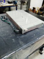
The cover is just placed there, not fixed down. I'm waiting on my thermally conductive epoxy resin to arrive for that.
 
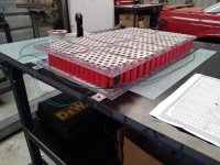
So all 4 modules are assembled waiting on the tabs to be welded.

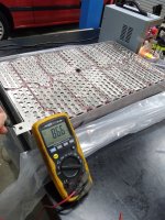
4 modules at 24s23p means 4416 busbar welds and 4416 cell welds. My Sunkko welder takes about 1 minute per tab cause it needs about 8 zaps, and it gets rather hot. So that equates to around two week work :?

Time for a welding party...

first welding.jpg
more welds.jpg
 
Wanna come to Perth for a working holiday? 😂 Bring your welded though :wink:
 
jonescg said:
Wanna come to Perth for a working holiday? 😂 Bring your welded though :wink:
Ha! That would be fun...I just started a new job (work in IT) so no holidays for me for a while!
Tell you what though, I dread the day my JP welder dies...with no more being made and I haven't seen any that come close in capability and versatility for the cost yet.

Cheers
 
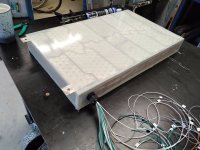
First side of the first module welded, and now sealed up with thermally conductive resin and a sheet of G10FR4 on the bottom.
first module bottom side welded sml.jpg
bottom layer on.jpg
 
top side welded.jpg
Module glued up.jpg
More or less finished this module. One down three to go. The biggest headache is the lousy connection between the nickel tab and the nickel plated aluminium busbar. Wherever the plating surface is badly discoloured it *refuses* to stick. I ended up getting creative with the contacts on the last busbar...
Nickel plated aly sucks.jpg
 
Looking good. I reckon this is a good standard for a DIY pack this size and an approach I may one day copy if I ever do a car.
I know it's a bit late, but one idea I just had that could make the welding a bit easier is to use a small dab of conductive carbon grease between the tab and the plate before welding. Worth a shot IMO.

Cheers
 
Chris, can you describe the process for encapsulating the cells? Was it hard? What are the thermal properties? (thanks)
 
Frank said:
Chris, can you describe the process for encapsulating the cells? Was it hard? What are the thermal properties? (thanks)

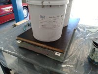
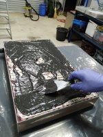
I've not yet fully encapsulated this module, but the ends have been done with a thermally conductive, electrically isolating epoxy resin. I basically spread out about 900 g of mixed resin and pressed the sheet of FR4 down onto it, eliminating any air pockets. Once it was nearly set, I flipped it over and lay it on the table. Then I welded up the top side and repeated the process, this time placing some mass on a couple of sheets of form ply to even out the pressure. It's set now, so the last thing to do is tape up the sides and fill the middle with some kind of free-flowing polyurethane resin as an encapsulant. But to get the stuff in, I'll have to drill the hole where the fill point was. I'll need a least 2 litres, so I might do two pours.
 
Thanks Chris.

Is the assumption that most of the heat is at the ends of the cells and the thermally conductive epoxy will move heat away from the cell body via the busbar? Do you think the FR4 might inhibit heat flow? Is the polyurethane absolutely necessary?

Sorry 'bout all the questions but I'm also exploring high output packs using cylindrical cells and heat management will be an issue. I'm trying to learn as much as I can from others people's experiences.
 
Yes the thermal conductivity of a cylindrical is 10 times higher in the axial plane than radially, so by focusing on pulling heat out through the ends you can get a very compact setup. The tabs are likely to be a hot spot, so soaking as much heat as possible from the busbar ends makes sense.
The polyurethane is mostly to help add rigidity and robustness, but also it soaks up heat really well due to its high (for a polymer) specific heat capacity. So tje module temperature shouldn't rise too quickly for the same amount of heat being generated.
The sheet of FR4 will impede the heat flow a little, yes. But its got a conductivity of 0.4 W/mK and its only 0.8 mm thick. Not ideal, but workable.
And given the DCIR of these cells, it will be getting hot if you push it.
 
Thanks for the info! I know water-resistance is important to you but I'm also wondering if you considered active air cooling of the busbars?
 
You answered your own question there :)

Too risky to have the busbars cooled directly with air. The tabs are not stuck to the busplates as well as I'd like them to be, so any opportunity for corrosion will only make those contacts worse. Ensuring the heat is uniformly spread throughout the battery is the best I can hope for, and the thermally conductive resin should help with this.
thermal epoxy going on.jpg
 
Wow, that looks messy. Bet it smells bad too.

I built a much smaller pack with a similar idea. The ends of the cells have a layer of glue between them and the case so there is a pathway for the heat to escape that does not have an air gap. On mine, the case is in the wind, so the batteries get effectively cooled.
 
Chris - thanks again, good points. There seems to be value in minimizing risk of welds breaking.

Can you estimate how much extra weight the epoxy adds? Did you consider eliminating the FR4 and relying on the epoxy for electrical insulation? As you said earlier, perhaps the FR4 doesn't add that much of a barrier anyway.
 
I think all the resin will add about 3 kg to an othwise 27 kg module.

Oh, and I learned this neat trick: https://youtu.be/2rsgbTUxYLE
 
Back
Top