
You are using an out of date browser. It may not display this or other websites correctly.
You should upgrade or use an alternative browser.
You should upgrade or use an alternative browser.
jonescg's NEW electric racebike BUILD thread!
- Thread starter jonescg
- Start date
jonescg
100 MW
Another bike day today. I had to replace the radiator of the Blackbird since it had been leaking for about 2 years, and I'd overheated it on more than one occasion. Finally got around to it.
While I was working on radiators, I decided to remove the nosecone radiator from Voltron. I'm pretty sure it wasn't doing anything, and it just make things messier up the front. I re-filled the loop with rain water and purged the pumps of any air, ready to roll.
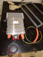
The new HVIL connector was fitted to the existing flex 50 mm2 cable and heat-shrunk, then covered in split orange conduit.
I made a good fist of the LV wiring loom for inside the battery, but I'm not done there yet. Time for a new PCB with the correct (not jury-rigged) through-hole spacings for the pre-charge relay. You can see it fell off amongst all my rough handling. I've got HVIL connectors now too, so the challenge will be making it all fit and look sort of neat.
I did a video of how it all works.
While I was working on radiators, I decided to remove the nosecone radiator from Voltron. I'm pretty sure it wasn't doing anything, and it just make things messier up the front. I re-filled the loop with rain water and purged the pumps of any air, ready to roll.
The new HVIL connector was fitted to the existing flex 50 mm2 cable and heat-shrunk, then covered in split orange conduit.
I made a good fist of the LV wiring loom for inside the battery, but I'm not done there yet. Time for a new PCB with the correct (not jury-rigged) through-hole spacings for the pre-charge relay. You can see it fell off amongst all my rough handling. I've got HVIL connectors now too, so the challenge will be making it all fit and look sort of neat.
I did a video of how it all works.
Attachments
jonescg
100 MW
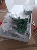
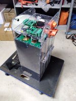
Looks like the BMS boards will be a tight fit, but efficient. 16 all up, with each double-stacked group covering 21 cells. IDC ribbon goes down to the cell block below.
Attachments
jonescg
100 MW
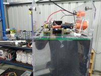
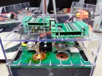
After three attempts I now know what the ideal length of ribbon is. 125 mm. AMHIK...
Those two pairs of green wires are the thermistors which call for an SMD resistor change. I used 100 k NTCs but the BMS was expecting 10 k. Finally, these modules will have cell potentials on them, so it's feasible to make contact with a hefty voltage if you're not paying attention. I might try and devise some dividers, or modularise the four boards per cell block so it's lower risk.
Edited to add an image. That's a busy BMS.
Attachments
Last edited:
jonescg
100 MW
harrisonpatm
10 kW
- Joined
- Aug 8, 2022
- Messages
- 830
I apologize if you've answered this earlier in the thread. But can you confirm, is the final draft of the battery case going to remain polycarbonate? If so, is that strong enough? And how is it mounted/secured to the frame?
I'm considering polycarbonate box in some sort of steel "cage" for a future build, looking for insight.
I'm considering polycarbonate box in some sort of steel "cage" for a future build, looking for insight.
jonescg
100 MW
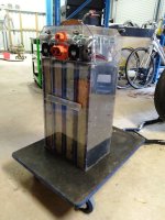
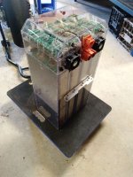
Yes, all 4 battery modules, weighing 17.2 kg each, sit inside an enclosure made of clear polycarbonate. The front and rear panels are 4.5 mm while the left and right sides are 3 mm. There's a selt tapping stainless steel screw every 40 mm or so, so it's pretty rigid.I apologize if you've answered this earlier in the thread. But can you confirm, is the final draft of the battery case going to remain polycarbonate? If so, is that strong enough? And how is it mounted/secured to the frame?
I'm considering polycarbonate box in some sort of steel "cage" for a future build, looking for insight.
I like PC because it's tough, it's heat and electricity- proof, and its clear, so you can see shit about to happen, hopefully before it happens.
Last edited:
jonescg
100 MW
Oh as for how it's mounted inside the frame, it sits in the cradle which is part of the subframe. It is also held in position by mounts made of angle aluminium, within the chassis. Id say the cradle takes the bulk of the load though.
harrisonpatm
10 kW
- Joined
- Aug 8, 2022
- Messages
- 830
Oh, so the way you've joined the PC panel corners together is with fasteners? I was reading about solvent welding polycarbonate, but if you think the joints are tight enough if you use self tappers, I'll certainly take that under consideration. I usually prefer mechanical methods over chemical.There's a selt tapping stainless steel screw every 40 mm or so, so it's pretty rigid.
If you're screwing edges together, is that going to decrease it's waterproofing? Seems like it'd be easy for water to work its way in through the cracks/edges. Perhaps that not an issue for you, as your build is a limited-use performance machine, while I'm considering it for a daily commuter, potentially in rainy weather.
From this description, it sounds like the polycarbontate case is resting within a steel frame, rather than being fastened to it. Which is probably the best way if you're using plastic structurally. It's what I had imagined, nice to hear you confirming it.It is also held in position by mounts made of angle aluminium, within the chassis.
jonescg
100 MW
Yeah I wouldn't describe this battery as waterproof. I've added slots at the base and up the shelves of the pack to allow airflow to hopefully take some of the heat out of the pack while on charge. You could conceivably put silicone sealant up the sides of the case to make it a bit more water resistant, but's it's probably IP54 at best. Glue is permanent, and if I ever needed to work on this pack I can pull it all apart. It won't be as good going back together, but hopefully that never happens...
SpeedRacer93
10 mW
- Joined
- Jun 12, 2018
- Messages
- 23
Chris, I have been researching immersion cooling of batteries and it may help you pull full amps from your pack. You would need to build a sealed battery box and add a pump, radiator, and the fluid which all adds weight. Weight vs more power....
You could use laboratory deionized water, mineral oil, transformer oil, or a commercial product like Ampcool. You could also use ATF designed for hybrids where the electric motor is inside the transmission but I need to check its flammability rating.
Here is a video about a college group that built a immersion cooled motorcycle used for TT races. They also have a 45 minute video going into some details on it. Being a college project there must also be papers written on it.
jonescg
100 MW
I have looked into it - Novec looks to be the most viable fluid, but it ain't cheap. It also leaks through gaps and seals like crazy, in part to its very low viscosity. I'd never use water - way too risky. I'm not sure if the polycarb enclosure would satisfactorily constrain the fluid, or would it cause any stress points to continue to grow.
SpeedRacer93
10 mW
- Joined
- Jun 12, 2018
- Messages
- 23
3M is going to stop making Novec in 2025 so prices have been going up.I have looked into it - Novec looks to be the most viable fluid, but it ain't cheap. It also leaks through gaps and seals like crazy, in part to its very low viscosity. I'd never use water - way too risky. I'm not sure if the polycarb enclosure would satisfactorily constrain the fluid, or would it cause any stress points to continue to grow.
In a previous life we had a DI water system and we used the DI water to wash computer equipment in a data center. We tested running a PC fully immersed in the DI water. Nothing high voltage but the dielectric constant and dielectric strength is higher then Novec and other immersion fluids. The trouble with DI water is keeping it pure. Most immersion cooling fluids have the same issue keeping it pure.
Yeah building the case would be the hardest part. You would need PTFE gaskets and pressure test it for leaks. Also not sure on the reaction to the polycarb case over time.
I know there are a couple production battery systems using immersion cooling but nothing to a large scale yet. I know John Deere and Faraday Future plan to use it.
SpeedRacer93
10 mW
- Joined
- Jun 12, 2018
- Messages
- 23
Well I just found a 2017-2019 thread that you started that talked all about cooling of LiPo pouch cells. Looks like you did a some testing and a lot of ideas came up, even DI, ATF, and Novec.

 endless-sphere.com
I think immersion cooling would work but for the weight and cost you may be better off adding another set of P cells to the pack.
It looks like prices for AMPCool are about $350USD for a 20Liter pail here in the US.
The "thermal management of LiPo" thread!
Hi guys, I have been building LiPo packs from individual cells for a couple of years now, and I believe I have a solid system. I can discharge my 15 Ah packs at 13C and they don't get warm until the last ~25% of the discharge. Now, I have generally not found them to get particularly hot, but...
I think immersion cooling would work but for the weight and cost you may be better off adding another set of P cells to the pack.
It looks like prices for AMPCool are about $350USD for a 20Liter pail here in the US.
DaLanMan
10 kW
the pics look awesome... But I have bad news for you.. it appears you have a bunch of junk in your trunk.
jonescg
100 MW
If you're calling me fat... you're correct.
DaLanMan
10 kW
Hey, It was totally not a case of the lardass calling the chubby butt...
jonescg
100 MW
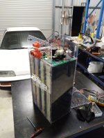
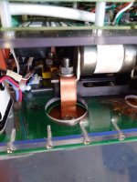
BMS shelf is now complete. Each of the 16 modules monitors 10 or 11 cells. The boards are linked by a 2-wire IsoSPI coms cable and a shield wire, which I'm told seems to introduce more noise than it protects from...
Still, it's a very busy board. The HV shelf and the LV wiring loom to manage it is also pretty busy, so I did a better job of the loom and I'll notch the BMS shelf to avoid needing to thread any cables through the shelf. I might also drill some 20 mm holes in the front wall so that I can poke a finger in and push the BMS IDC connectors down firmly. Might be a bit hard through the top shelf.
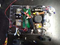
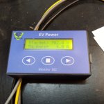
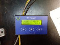
I also made a start on the new liquid cooled 7 kW off-board charger. I want to turn this into a 'power board' which is not just the main source of DC charging power, but also the 12 V stuff, and a few spare GPOs for tyre warmers, laptops and other things you need to power at a racetrack. The charger is CAN controlled, and EV-Power have provided a really neat little CAN-Charge gizmo meaning I can set volts and amps for any battery pack within a set range, up to 800 V DC.
Still, it's a very busy board. The HV shelf and the LV wiring loom to manage it is also pretty busy, so I did a better job of the loom and I'll notch the BMS shelf to avoid needing to thread any cables through the shelf. I might also drill some 20 mm holes in the front wall so that I can poke a finger in and push the BMS IDC connectors down firmly. Might be a bit hard through the top shelf.
I also made a start on the new liquid cooled 7 kW off-board charger. I want to turn this into a 'power board' which is not just the main source of DC charging power, but also the 12 V stuff, and a few spare GPOs for tyre warmers, laptops and other things you need to power at a racetrack. The charger is CAN controlled, and EV-Power have provided a really neat little CAN-Charge gizmo meaning I can set volts and amps for any battery pack within a set range, up to 800 V DC.
Attachments
From-A-To-B
100 W
Some of us are still trying to figure out how to mount our Schwalbe Marathons with the tread pointed forward, and JonesCG is out here doing the most.
Well done — I’m consistently impressed with your work and am grateful that you bring us along!
Well done — I’m consistently impressed with your work and am grateful that you bring us along!
Last edited:
jonescg
100 MW
Final weigh-in! Drumroll.....
77.5 kg. Not bad for 12 kWh.
I think it will be a little more in reality as there was still some light tension on the hoist when I lowered it onto the scales, but anything under 80 kg is an achievement.
Last things to do are to hook up the final HV buslinks and drop it into the bike. The BMS is still some ways off working, but I should be able to make it work for long enough to get the settings right.
Attachments
jonescg
100 MW
It’s alive!
Nice work
Nice work
jonescg
100 MW
jonescg
100 MW
Did a blockie or two - she still goes hard 
Electrically I only need to get the BMS working properly, and that's sorted. The front end needs a refresh since the weight has gone up by 18 kg or so. Things like stiffer springs and new fork oil will make a difference.
And I can say I finished it in 2023! Just.
Electrically I only need to get the BMS working properly, and that's sorted. The front end needs a refresh since the weight has gone up by 18 kg or so. Things like stiffer springs and new fork oil will make a difference.
And I can say I finished it in 2023! Just.
Attachments
Similar threads
- Replies
- 4
- Views
- 818
- Replies
- 52
- Views
- 1,810
- Replies
- 7
- Views
- 1,305
- Replies
- 4
- Views
- 447
- Replies
- 17
- Views
- 2,695