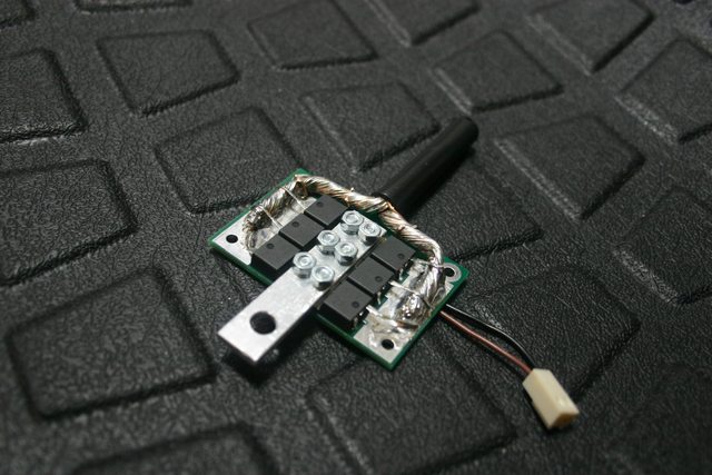
JP spot welder

BYqSXt8Z said:
sweet... would this be usable with a microwave inverter instead of the batteries? Not a deal breaker (by a long shot), but would be good to know.


No, this will only work with battery power :)


Ohbse said:
No, this is for battery power source only. Transformer based welders suck.

Congratulations on bringing this to the public! This looks really, really great.

I built a very similar welder using 7 irf1324 powered by two 60ah 900CCA starters in parallel and it works great for welding 0.3mm Nickel. Other than my knockoff arduino failing randomly I have had zero failures while building batteries and it has done now many thousands of welds. No reason to believe this won't be even more reliable. Now hopefully we can stop seeing so many threads asking about DN-10 and other dodgy transformer based options.

Thank you, yes you are right! I believe this works much better than transformer based welders, it also offers much better adjustment.
 
You've made something useful here, and I'm looking forward to supporting your efforts!

I don't own a car or a car battery (thankfully) but I do have 30 A123 M1 26650 cells lying around looking for a job to do.

If I have calculated correctly, your setup using two 45 Ah 12 volt batteries in parallel has 720 cold cranking amps. This implies an internal resistance of 16.7 milli ohms.

Each A123 M1 cell is rated at 10 milli Ohm internal resistance according to the data sheet. So, three in series should be 30 milli ohms, then paralleling two sets of three in series should result in 15 milli ohms of internal resistance for the 3S2P pack. This battery would provide 10 volts rather than the 12-14 volts a car battery would provide, so it is quite similar to your two parallel car battery setup. I think it should work well, but I will need to make thick connections between the cells in order to support the current flow. Do you see any other problems with using a 3S2P A123 pack to power the welder?

Back when I was brand new to all this, I blew a divet out of a thick screwdriver blade while building an A123 pack, I didn't realize at the time how close I had come to building a welder!!!

Now for the little questions-

Are you ready to ship these once you return from your trip?

How much will you charge for 6 replacement FETs for the high power version? I do like to experiment...

Could you also sell a barrel jack to solder onto another 12 volt pack to supply logic power? (never hurts to ask)

It looks like the FETs are covered in solder, I've only done soldering with a 40 watt pen style unit- I doubt that will handle removing the FETs from your board and soldering in new ones, what soldering tool do you recommend to make that job quick and easy?
 
silentflight said:
You've made something useful here, and I'm looking forward to supporting your efforts!

Thank you :)!

I don't own a car or a car battery (thankfully) but I do have 30 A123 M1 26650 cells lying around looking for a job to do.

If I have calculated correctly, your setup using two 45 Ah 12 volt batteries in parallel has 720 cold cranking amps. This implies an internal resistance of 16.7 milli ohms.

I think your calculation is a bit of, I get around 6.5 mohm. ( Ri=Udrop/I, R=(12-7)/(380*2)= 6.578 mohm )


Each A123 M1 cell is rated at 10 milli Ohm internal resistance according to the data sheet. So, three in series should be 30 milli ohms, then paralleling two sets of three in series should result in 15 milli ohms of internal resistance for the 3S2P pack. This battery would provide 10 volts rather than the 12-14 volts a car battery would provide, so it is quite similar to your two parallel car battery setup. I think it should work well, but I will need to make thick connections between the cells in order to support the current flow. Do you see any other problems with using a 3S2P A123 pack to power the welder?

I don't see a problem, but you must take into consideration that every connection you make adds additional resistance.


Back when I was brand new to all this, I blew a divet out of a thick screwdriver blade while building an A123 pack, I didn't realize at the time how close I had come to building a welder!!!

Yes, I'm sure they can punch, you should do experiments if you have time and will to do it. :) But I can't give you definite answer, because I've only used starter batteries.


Now for the little questions-

Are you ready to ship these once you return from your trip?

Yes, I am. That will be 4. May because 1. May is a holiday, and there's weekend after that.


How much will you charge for 6 replacement FETs for the high power version? I do like to experiment...

I'm not 100% sure, probably around 2.5$ for one 1324 fet.


Could you also sell a barrel jack to solder onto another 12 volt pack to supply logic power? (never hurts to ask)

Sure, no problem!


It looks like the FETs are covered in solder, I've only done soldering with a 40 watt pen style unit- I doubt that will handle removing the FETs from your board and soldering in new ones, what soldering tool do you recommend to make that job quick and easy?

Yes, you should use very strong soldering iron, at least 100 W with big tip. 150 W would be good. But I think that there wont be need for doing that :)


Here you go, my answers are in bold.

One more thing to add, I'm working on a slightly different way to attach cable to mosfet drains, without soldering, so it would be easier to remove them. It will actually be aluminum bar screwed with six bolts. I already have PCB designed to support that.
 
riba2233 said:
I think your calculation is a bit of, I get around 6.5 mohm. ( Ri=Udrop/I, R=(12-7)/(380*2)= 6.578 mohm )

Let's see if I can untangle my errors. I hope this helps a few other people waiting to buy and hoping to use their own lithium cells to drive your spot welder.

First, each battery is capable of 380 cold cranking amps, not 360.

Second, in Europe voltage is U, not V. Thank you, Gulyas! (my freshman physics prof in Budapest- all errors are my responsibility, Gulyas rocked).

Third, lead acid batteries sag like mad, so the current is supplied at 7 volts, not 12, and that all adds up to 6.57 milliohms for the two car batteries in parallel rather than 16.7 in my previous calculation.

My only question now is how did you measure the voltage to be 7 during such a brief time- only a few milliseconds? Sorry for taking this off topic.

So, now I am thinking I will try a 3S4P A123 pack with an ideal internal resistance of 7.5 milliohms. I will maybe increase it to 3S5P or 3S6P if the connections I make between cells add too much resistance.

Now, back to the real topic of this thread with an interesting question for all concerned- what does the JP stand for in the name of the welder?
 
silentflight said:
riba2233 said:
I think your calculation is a bit of, I get around 6.5 mohm. ( Ri=Udrop/I, R=(12-7)/(380*2)= 6.578 mohm )

Let's see if I can untangle my errors. I hope this helps a few other people waiting to buy and hoping to use their own lithium cells to drive your spot welder.

First, each battery is capable of 380 cold cranking amps, not 360.

Second, in Europe voltage is U, not V. Thank you, Gulyas! (my freshman physics prof in Budapest- all errors are my responsibility, Gulyas rocked).

Third, lead acid batteries sag like mad, so the current is supplied at 7 volts, not 12, and that all adds up to 6.57 milliohms for the two car batteries in parallel rather than 16.7 in my previous calculation.

My only question now is how did you measure the voltage to be 7 during such a brief time- only a few milliseconds? Sorry for taking this off topic.

So, now I am thinking I will try a 3S4P A123 pack with an ideal internal resistance of 7.5 milliohms. I will maybe increase it to 3S5P or 3S6P if the connections I make between cells add too much resistance.

Now, back to the real topic of this thread with an interesting question for all concerned- what does the JP stand for in the name of the welder?

7.5 is too high. my entire circuit including battery all connection and electrodes and contacts to weld is ~6.7 mohm.

lead acid wont sag under pulse load like this. a 380 CCA battery would be ~4mohm by a quick guess.
CCA is done by measuring voltage after 10 seconds of sustained current AT 0°F. this welder only does 0.02 seconds at 75°F. :)
 
silentflight said:
Let's see if I can untangle my errors. I hope this helps a few other people waiting to buy and hoping to use their own lithium cells to drive your spot welder.

First, each battery is capable of 380 cold cranking amps, not 360.

Second, in Europe voltage is U, not V. Thank you, Gulyas! (my freshman physics prof in Budapest- all errors are my responsibility, Gulyas rocked).

Third, lead acid batteries sag like mad, so the current is supplied at 7 volts, not 12, and that all adds up to 6.57 milliohms for the two car batteries in parallel rather than 16.7 in my previous calculation.

My only question now is how did you measure the voltage to be 7 during such a brief time- only a few milliseconds? Sorry for taking this off topic.

So, now I am thinking I will try a 3S4P A123 pack with an ideal internal resistance of 7.5 milliohms. I will maybe increase it to 3S5P or 3S6P if the connections I make between cells add too much resistance.

Now, back to the real topic of this thread with an interesting question for all concerned- what does the JP stand for in the name of the welder?

Yes, you got everything right! I didn't measure if they drop to 7 V, but that is what the standard suggest (it's how many amps battery can supply without dropping to more than 7 volts, more or less). So in reality it is possible that they drop even less, and thus have even lower Ri.

JP are mine initials, guess I wasn't to imaginative when I was giving the name, but I wanted to give it some name at least.
 
okashira said:
7.5 is too high. my entire circuit including battery all connection and electrodes and contacts to weld is ~6.7 mohm.

lead acid wont sag under pulse load like this. a 380 CCA battery would be ~4mohm by a quick guess.
CCA is done by measuring voltage after 10 seconds of sustained current AT 0°F. this welder only does 0.02 seconds at 75°F. :)


You are right, voltage drop could be even less. When I get home I will borrow an oscilloscope and measure it exactly if someone wants to know.
 
okashira said:
7.5 is too high. my entire circuit including battery all connection and electrodes and contacts to weld is ~6.7 mohm

Hello okashira- spoken like a man who might have an entire Tesla module at his disposal! I wonder about that module you use to drive your welder- I believe you said it was 2S and 330Ah. At about 3.3Ah / cell, would that mean you are using a 2S100P ! ! 18650 pack to weld with? I can't match that!

I guess the connections in the Tesla module weren't designed to deliver this kind of current, but they hold up alright during such short bursts, is that correct?

You mentioned in your other thread that you blew some MOSFETs early on, (congratulations! :twisted: ) would you mind sharing exactly what pack configuration and MOSFET combinations resulted in blown FETs?


riba2233 said:
You are right, voltage drop could be even less. When I get home I will borrow an oscilloscope and measure it exactly if someone wants to know.

JP ! - I would like to know, in order to get a closer estimate of the Ri of your battery setup, but if it takes much time or trouble, I understand you are busy making interesting things as well! -edit- Actually, a screen shot showing the shape of the burst and the rise and fall of the voltage might be of general interest. I think a thread discussing the technical aspects of this welder in general should become a topic over in the Battery Tech section of the sphere.

I will buy an oscilloscope when I'm done with school. By then they will be the size of a cracker and cost about the same. :wink:
 
silentflight said:
okashira said:
7.5 is too high. my entire circuit including battery all connection and electrodes and contacts to weld is ~6.7 mohm

Hello okashira- spoken like a man who might have an entire Tesla module at his disposal! I wonder about that module you use to drive your welder- I believe you said it was 2S and 330Ah. At about 3.3Ah / cell, would that mean you are using a 2S100P ! ! 18650 pack to weld with? I can't match that!

I guess the connections in the Tesla module weren't designed to deliver this kind of current, but they hold up alright during such short bursts, is that correct?

You mentioned in your other thread that you blew some MOSFETs early on, (congratulations! :twisted: ) would you mind sharing exactly what pack configuration and MOSFET combinations resulted in blown FETs?


riba2233 said:
You are right, voltage drop could be even less. When I get home I will borrow an oscilloscope and measure it exactly if someone wants to know.

JP ! - I would like to know, in order to get a closer estimate of the Ri of your battery setup, but if it takes much time or trouble, I understand you are busy making interesting things as well! -edit- Actually, a screen shot showing the shape of the burst and the rise and fall of the voltage might be of general interest. I think a thread discussing the technical aspects of this welder in general should become a topic over in the Battery Tech section of the sphere.

I will buy an oscilloscope when I'm done with school. By then they will be the size of a cracker and cost about the same. :wink:


whoops, sorry, it's only 230Ah. :oops: 74p.
Actually, the connections are suited just fine to that current.

my 4 awg 25mm2 wire heats up more then the connections, which stay nice and cool. I have them sanded and clamped down nicely.

The mosfets I was using were a much weaker kind, smaller package, different design.
 
silentflight said:
You mentioned in your other thread that you blew some MOSFETs early on, (congratulations! :twisted: ) would you mind sharing exactly what pack configuration and MOSFET combinations resulted in blown FETs?


JP ! - I would like to know, in order to get a closer estimate of the Ri of your battery setup, but if it takes much time or trouble, I understand you are busy making interesting things as well! -edit- Actually, a screen shot showing the shape of the burst and the rise and fall of the voltage might be of general interest. I think a thread discussing the technical aspects of this welder in general should become a topic over in the Battery Tech section of the sphere.

I will buy an oscilloscope when I'm done with school. By then they will be the size of a cracker and cost about the same. :wink:

As okashira said - blown mosfets were on older design, now I use different type and that wont happen anymore.

It's not a problem for me, when I borrow oscilloscope, you'll see everything! I have already measured some values, rise time is about 150 ns, and fall is actually much longer, but all of this in not important in this case, because there is no switching, only two pulses which are in milliseconds, and rise and fall times are negligible compared to the whole pulse.
 
riba2233 said:
One more thing to add, I'm working on a slightly different way to attach cable to mosfet drains, without soldering, so it would be easier to remove them. It will actually be aluminum bar screwed with six bolts. I already have PCB designed to support that.

JP Spot Welder 2.0? I'll wait for that one. :D
 
I am most interested in the spot welder (& look forward to the training video as this is new to me) One thing does worry me slightly, the evolution of Hydrogen gas within the automotive battery. Granted this is at its worst during charging (& indeed overcharging!) but I read from this that both H2 & O2 are evolved in a mixture at all times up to a point. http://www.battcon.com/papersfinal2008/odonnellpaper2008proof_6.pdf
I just wondered if the large battery leads should be longer to move the sparks of welding further from the large battery, also if this is a process more safely done in the open air so the H2 gas can never form the 4% concentration needed to ignite. (H2 being lighter than air it will rise & disperse) I am probably being over cautious here but remember being told never to smoke near back up batteries, & that they were to be connected & disconnected using insulated spanners (wrenches) to prevent any spark near them!
Other than that I will look under the van hood to see what battery I have, as this will decide which model suits

On another note is it practical to make 4P cell groups in holders, then mechanically connect each group to the next, reason being that one failing 18650 cell (runt) can be more easily identified & replaced than if all are spot welded to one another
 
Pete1961 said:
I am most interested in the spot welder (& look forward to the training video as this is new to me) One thing does worry me slightly, the evolution of Hydrogen gas within the automotive battery. Granted this is at its worst during charging (& indeed overcharging!) but I read from this that both H2 & O2 are evolved in a mixture at all times up to a point. http://www.battcon.com/papersfinal2008/odonnellpaper2008proof_6.pdf
I just wondered if the large battery leads should be longer to move the sparks of welding further from the large battery, also if this is a process more safely done in the open air so the H2 gas can never form the 4% concentration needed to ignite. (H2 being lighter than air it will rise & disperse) I am probably being over cautious here but remember being told never to smoke near back up batteries, & that they were to be connected & disconnected using insulated spanners (wrenches) to prevent any spark near them!
Other than that I will look under the van hood to see what battery I have, as this will decide which model suits

On another note is it practical to make 4P cell groups in holders, then mechanically connect each group to the next, reason being that one failing 18650 cell (runt) can be more easily identified & replaced than if all are spot welded to one another

I actually don't think the hydrogen is a problem at all, unless you keep the battery enclosed or something. As long as it's a large room you will be ok. Also, dont charge the battery while welding. float charge at best, dont charge at all when welding
I think they will only gas when charging ...

Or use a Model S module. Works great. ;)
 
No worries then re hydrogen. Thanks, I have two more questions:-
Can this weld 26650 cells & 36650 cells - if they become a good option re the improvements in performance that 18650 cells have seen ( I am thinking of the lower internal resistance of a bigger cell??)
Also can it weld NiMh NiCd & NiZn small cylindrical cells? I am thinking of a secondary market rebuilding power tool battery packs, the cells are readily obtainable. This would help finance owning the welder

Leaving the above on one side, I estimate that the welder would pay for itself building three batteries vs having to buy ready tagged cells.
I may wait for the newer PCB model with easy replace Mosfets, but count me as interested
 
Pete1961 said:
No worries then re hydrogen. Thanks, I have two more questions:-
Can this weld 26650 cells & 36650 cells - if they become a good option re the improvements in performance that 18650 cells have seen ( I am thinking of the lower internal resistance of a bigger cell??)
Also can it weld NiMh NiCd & NiZn small cylindrical cells? I am thinking of a secondary market rebuilding power tool battery packs, the cells are readily obtainable. This would help finance owning the welder

Leaving the above on one side, I estimate that the welder would pay for itself building three batteries vs having to buy ready tagged cells.
I may wait for the newer PCB model with easy replace Mosfets, but count me as interested

Yeah, 26650 shouldn't be a probelm, and for 36650 I can't be sure, haven't tried, but I think it will. Other smaller cells and Ni cells shouldn't be a problem! :)

Yes, this thing can pay off itself very easily.

There wont be newer PCB model, actual one already offers the same. You will see picture later today, I'll update the first post. Everyone who has ordered and who orders will get this update :) (bolted conductor (Al profile) on mosfet drains instead of soldered cable)
 
Ok, here is is:

3NOyxdGl.jpg


That's how it's gone be done from now on. This makes mosfets easily replaceable (if there is need to, of course).
 
dnmun said:
just a little overkill on that conductor to the source legs! the legs look like toothpicks stuck in a log.


Well all cables are 25mm2, and so is this one, it felt natural to use same gauge at this spot too :)

ohzee said:
hah looks good. Can't wait to get my hands on one.

Thanks! :)

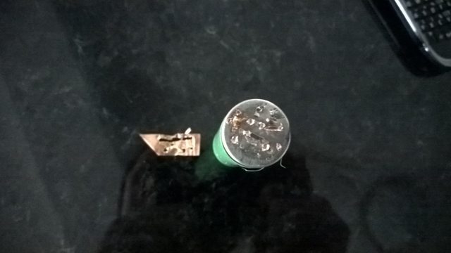
Here is some 0.1 mm copper after tearing from cell, there are holes on all of the places that were welded:

KyaQKePl.jpg


I know it's a bad quality image, but this was just quick, I will do more and better pictures tomorrow or day after.
 
Back
Top