LTC6811 Implementation Thread

Patrick, what do you need opened in Altium? My old version opened raphael chang's files. If you need something, let me know and I will try to snag it for you and put into pdf or something.
 
Look at Altium Circuit Studio, a slightly less fancy version than Designer, but almost the same user interface. It does everything you need, autorouting,3D, same as Designer, it probably uses the same underlying engine. You don't need a $10K layout/schematic system, that is for laying out motherboards 8 layer+ boards
Altium Circuit Studio is being sold for 500 dollars via Newark/Element14 if you are switching from Eagle. Everyone is jumping ship after Autodesk bought Eagle and changed it to subscription based only. Here's the link: http://www.altium.com/eagle-switch/circuitstudio/
You can download a 30 day trial of Circuit Studio. It will import eagle stuff and import Altium Designer files if you export it from Designer.

And if that's not cheap enough, another option is Altium CircuitMaker which is exactly the same as Circuit Studio and is completely free, no restrictions, except it is partly cloud-based and more collaborative, multiple people can edit stuff at the same time if you want. They use a different online parts library concept with Octopart and kind of a shared library that everyone contributes to.
 
Thanks for the tips guys.

My primary concern is the time investment... I think I have gown out of Eagle but engineering hours are precious. The engineering company I am working with now does not want to invest the hours developing something which is available (understandable).

As for BMS progress...
We went sideways for a couple weeks looking into leveraging work already done.
Even if things pan out in that river... it does not look like I would be able to open a channel for general DIY use so we are still on for this adventure.

That said -
Adventures like this are causing me problems already as designer(s) are hesitant to give me hands on with their hardware for fear of IP being run off with.
That's par for the course in the Bay tho... frigging McDonald's wants me to sign an NDA before opening up their hamburger to apply ketchup.

2005
2006
2007
2008
2009
2010
2011
2012
2013
2014
2015
2016
2017

WTF?
Really?
Still no BMS "widely available" that scales and does all the right stuff for the right quiescent current?

I inquired about the Adapto BMS and found a black hole of information.
I have quit working on projects like this twice in anticipation of seeing someone hit it out of the park.

Every major Auto maker now has a "good bms" in their lineup... maybe its time to nip off their Master and start using their slave nodes as salvage items... :idea:

-methods
 
Did you see this one:
https://endless-sphere.com/forums/viewtopic.php?f=14&t=88676

The Chinese are coming close to making a BMS that doesn't suck.
 
bigmoose said:
Patrick, what do you need opened in Altium? My old version opened raphael chang's files. If you need something, let me know and I will try to snag it for you and put into pdf or something.

Could you export the PCB file to a 5.0 PCB file? This is what is needed to get the file into circuit studio.
Per this video:
https://www.youtube.com/watch?v=YAWBsShCId4&t=266s
 
velias said:
Look at Altium Circuit Studio, a slightly less fancy version than Designer, but almost the same user interface. It does everything you need, autorouting,3D, same as Designer, it probably uses the same underlying engine. You don't need a $10K layout/schematic system, that is for laying out motherboards 8 layer+ boards
Altium Circuit Studio is being sold for 500 dollars via Newark/Element14 if you are switching from Eagle. Everyone is jumping ship after Autodesk bought Eagle and changed it to subscription based only. Here's the link: http://www.altium.com/eagle-switch/circuitstudio/
You can download a 30 day trial of Circuit Studio. It will import eagle stuff and import Altium Designer files if you export it from Designer.

And if that's not cheap enough, another option is Altium CircuitMaker which is exactly the same as Circuit Studio and is completely free, no restrictions, except it is partly cloud-based and more collaborative, multiple people can edit stuff at the same time if you want. They use a different online parts library concept with Octopart and kind of a shared library that everyone contributes to.

Thanks I am looking at CircuitStudio now, might be worth it for the $500 deal.
If you have designer could you export the battman pcb file to a 5.0 pcb file???
Open the PCB, Save As, select format as 5.0 pcb file.

Here is a quick link to the pcb file to make it easy for you. I linked to the whole project earlier in the thread.
https://1drv.ms/u/s!AuqwBZb5n5Jqgpp4pTe1WZnFiiV_Ew
 
Uh... velias...

velias said:
Look at Altium Circuit Studio, a slightly less fancy version than Designer, but almost the same user interface. It does everything you need, autorouting,3D, same as Designer, it probably uses the same underlying engine. You don't need a $10K layout/schematic system, that is for laying out motherboards 8 layer+ boards
Altium Circuit Studio is being sold for 500 dollars via Newark/Element14 if you are switching from Eagle. Everyone is jumping ship after Autodesk bought Eagle and changed it to subscription based only. Here's the link: http://www.altium.com/eagle-switch/circuitstudio/
You can download a 30 day trial of Circuit Studio. It will import eagle stuff and import Altium Designer files if you export it from Designer.

And if that's not cheap enough, another option is Altium CircuitMaker which is exactly the same as Circuit Studio and is completely free, no restrictions, except it is partly cloud-based and more collaborative, multiple people can edit stuff at the same time if you want. They use a different online parts library concept with Octopart and kind of a shared library that everyone contributes to.

That was the best post I have read in like... A MONTH.
Thanks :D

I am all over it.

Here is the link to the AD / CD comparison
https://www.element14.com/community...designer-feature-and-specification-comparison

Here is a breakdown of the features which are not identical with a description of what they are:

note: ah... so they are freezing the old design, selling it cheap, and charging more for the latest improvements. I have always liked that model.
note: Using Eagle is like using a hammer for a Toothbursh... so I am not trying to pick Altium apart... just want to see which fancy features I will not get.

* Wire segment editing - I presume the ability to cut out a little part of a net leaving two new nets? Fine.

* Device sheets - Ah... thats a bummer... its like a persistent copy and paste.You can group common stuff and plop it down... hmmm... if it preserves the copper... (probably not)

* Design refactoring - yep... I dont do enough PCB work to warrantthis

* Advanced design variants - lol - totally out of my league. I just want to make a 4 layer PCB that doesn't suck

* Smart paste -I could see this being useful... if requirements are drawn up well one would like to be able to shift them over... oh well - I dont work for the man anymore.

* Blankets - meh, no biggie

* Specific no ERC
* Bus dragging
* Push while dragging
* Automatic neckdown
* Specctra interface
blah blah blah

Rigid flex support - that is a bummer
.
.
.

Non circular holes? Really guys... nah... dont even give engineers that option :roll: Does anyone even go to the manufacturing facility anymore these days? The non circular drills are all dull and you have to pay a resharpening fee every time you use them. So... dont care.

It does blind vias... :D

Yea - I have seen enough.
$500 is the kind of cash I would not mind spending on Altium.
I am going to do it before I invest any more time into Eagle.

Now - the only question is if I can sell enough of my old ebike junk to make it happen. I date an accountant now so... eh... I get to carry around the kind that jingles but not the kind that folds if you know what I mean :? .

Wait till you guys see the pics of my back yard. I finally went back and cleared out my warehouse... omfg... my back yard has 10 bikes, 2 trailers, and 5' of tires and wheels (stacked flat). Most of it is going to the Santa Cruz Bike Church... but some of it will be cleaned up and sold for a very good price on Craigs List.

Last night we stayed up late and got an Ebike running... pics later... it was an awesome grind. I pulled Justin's jalopy out of the pile, rigged it with the most sketch and corroded BC controller, and no-fuse, no bms wired up 4 hobby king packs. Its the second bike I have had a runaway with... (throttle not applied, bike goes)... but I am writing that up separate.

thanks!
-methods
 
methods said:
Uh... velias...

velias said:
Look at Altium Circuit Studio, a slightly less fancy version than Designer, but almost the same user interface. It does everything you need, autorouting,3D, same as Designer, it probably uses the same underlying engine. You don't need a $10K layout/schematic system, that is for laying out motherboards 8 layer+ boards
Altium Circuit Studio is being sold for 500 dollars via Newark/Element14 if you are switching from Eagle. Everyone is jumping ship after Autodesk bought Eagle and changed it to subscription based only. Here's the link: http://www.altium.com/eagle-switch/circuitstudio/
You can download a 30 day trial of Circuit Studio. It will import eagle stuff and import Altium Designer files if you export it from Designer.

And if that's not cheap enough, another option is Altium CircuitMaker which is exactly the same as Circuit Studio and is completely free, no restrictions, except it is partly cloud-based and more collaborative, multiple people can edit stuff at the same time if you want. They use a different online parts library concept with Octopart and kind of a shared library that everyone contributes to.

That was the best post I have read in like... A MONTH.
Thanks :D

I am all over it.

Here is the link to the AD / CD comparison
https://www.element14.com/community...designer-feature-and-specification-comparison

Here is a breakdown of the features which are not identical with a description of what they are:

note: ah... so they are freezing the old design, selling it cheap, and charging more for the latest improvements. I have always liked that model.
note: Using Eagle is like using a hammer for a Toothbursh... so I am not trying to pick Altium apart... just want to see which fancy features I will not get.

* Wire segment editing - I presume the ability to cut out a little part of a net leaving two new nets? Fine.

* Device sheets - Ah... thats a bummer... its like a persistent copy and paste.You can group common stuff and plop it down... hmmm... if it preserves the copper... (probably not)

* Design refactoring - yep... I dont do enough PCB work to warrantthis

* Advanced design variants - lol - totally out of my league. I just want to make a 4 layer PCB that doesn't suck

* Smart paste -I could see this being useful... if requirements are drawn up well one would like to be able to shift them over... oh well - I dont work for the man anymore.

* Blankets - meh, no biggie

* Specific no ERC
* Bus dragging
* Push while dragging
* Automatic neckdown
* Specctra interface
blah blah blah

Rigid flex support - that is a bummer
.
.
.

Non circular holes? Really guys... nah... dont even give engineers that option :roll: Does anyone even go to the manufacturing facility anymore these days? The non circular drills are all dull and you have to pay a resharpening fee every time you use them. So... dont care.

It does blind vias... :D

Yea - I have seen enough.
$500 is the kind of cash I would not mind spending on Altium.
I am going to do it before I invest any more time into Eagle.

Now - the only question is if I can sell enough of my old ebike junk to make it happen. I date an accountant now so... eh... I get to carry around the kind that jingles but not the kind that folds if you know what I mean :? .

Wait till you guys see the pics of my back yard. I finally went back and cleared out my warehouse... omfg... my back yard has 10 bikes, 2 trailers, and 5' of tires and wheels (stacked flat). Most of it is going to the Santa Cruz Bike Church... but some of it will be cleaned up and sold for a very good price on Craigs List.

Last night we stayed up late and got an Ebike running... pics later... it was an awesome grind. I pulled Justin's jalopy out of the pile, rigged it with the most sketch and corroded BC controller, and no-fuse, no bms wired up 4 hobby king packs. Its the second bike I have had a runaway with... (throttle not applied, bike goes)... but I am writing that up separate.

thanks!
-methods

Basically CS (circuit studio) is supposed to be a chopped down AD (altium designer) with tweaked interfaces to make it more beginner friendly.
It seems to be much better then designspark which is my only experience. lol. I think designspark is TERRIBLE so I am going to move away from it.
KiCad I think is the next best option (this one is free) OrCad and DipTrace also exist but don't seem to offer enough to justify paying over KiCad.

Please let me know if you get the battman pcb files exported from AD to 5.0 or 6.0 format for CS.
 
okashira said:
Could you export the PCB file to a 5.0 PCB file? This is what is needed to get the file into circuit studio.
Per this video:
https://www.youtube.com/watch?v=YAWBsShCId4&t=266s
Sorry, it looks like my Altium is so old it only exports to "Schematic Binary 4.0"
 
bigmoose said:
okashira said:
Could you export the PCB file to a 5.0 PCB file? This is what is needed to get the file into circuit studio.
Per this video:
https://www.youtube.com/watch?v=YAWBsShCId4&t=266s
Sorry, it looks like my Altium is so old it only exports to "Schematic Binary 4.0"

Are you sure you had the PCB and not the schematic file open?
I got the schematic imported okay... but PCB is different
 
Shop space and time. Help methods as he Needs some donations. Boys and girls drop this guy ( methods ) a little coin. Help grease the wheel.
 
Thanks Zip!

Its ok... I will spill some beans in that I have given up on the Contractors track and committed to returning to FTE work to support the family. As soon as I settle into a position where I am valued I will be able to turn the $1k/mo R&D budget back on and the license will be no trouble.

I will admit tho... that funds have been TIGHT while contracting. Customers call it "Cash FLOW issues" lol... I call it "Rent is Due".

So - I will shortly be hanging up my hat and returning to a Lab someplace.

Justin put it well way back in the day...
When we were importing containers and looking at business models... Justin questioned whether I had the discipline to be a good, stand alone, business man.

hmmm...

Well I can demonstrate EXTREME discipline when I want to, but the domain of Business is not really an area I get excited about... so... yea... I probably do not have the discipline required to be a successful stand alone business man.

I mean... If I have $20k sitting around... and I see a wrecked Tesla for $9k... uh... YOU KNOW I am going to buy that thing... right?
Even if it means my funds are tied up for 2 months... or 2 years... uh... I am just more interested in tinkering than I am in profiting.

That mixed with my belief that "pigeonholing" people is contemptible and punishable by public flogging... well.. yea... I am just never going to be a profiteer.

So - off to work I go.
Glad to... this has been the most stressful segment of my entire life.
The last 5 years... uh... I learned more lessons than you can shake a stick at.
No more lessons please :D I need some time to let the information sink in.

Anyhow - Zip shot me $20 out of the blue for some comedy and I appreciated it. Very cool... hopefully I will be able to return it to him at some point in the future.
Maybe in the form of a tester BMS???

-methods
 
Patrick I like trying to follow and learn you bring a lot to E.S. Teh bms would be in a better testers hands then mine. Now put the paper bag down, screw the cap on and get to work. Lol
I have to get some garage time right now. Out
 
Oh... you asked for it... :mrgreen:
I am going to upload all the pics we took last night. :twisted:

We were up past the witching hour building an ebike out of the tangled wreck of old broken ebikes in the back yard.
2hrs... with Kimberly helping @ 100%...
Cutting off rusty switches, pouring water out of controllers, pumping air into tires, hacking throttle wires...

We went from nothing to something - then took it for a ride in the rain.

-methods
 
Ok - so back on this.

I ran the "hardware design variant" from yesteryear all the way through the extrusion and it does not meet requirements.
This is the path forward and I am going with it.

The LTC6811 is one hell of an intimidating data sheet. Anyone who thinks they will just prance in and get it working is dreaming.... unless the code snippets they are now providing solve most of the riddle for you... which they may. I dug up my old LTC code and I will probably use bits and pieces of that along with the demo code they are promoting. This time around I am going to keep the code clean and release it out of respect for Arduino and all who have released their code.

At this point I am down selecting on components.
You may recall... We touched on the subject before and it is always a subject for debate: Balancing and noise filtering

You can get away clean with none... and you can use way too much... and every part on the board is time and money.


Three paths forward:

1) Internal balancing. We size the RC filter resistor to about 50 ohms

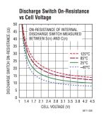
Reality not maximums.png

REMINDER: PAY ATTENTION WHILE READING LTC DATA SHEETS. FOLLOW THE GRAPHS, NOT THE PROSE
As... the prose would lead you to believe that the internal fets could reach 25 ohms... which they will not.

We will see between 10ohms and 14ohms of inline resistance on those fets... so we will set the RC resistance to 50 ohms.
Worst case (ish to avoid adding double margin) we should see 60mA... so a clean quarter watt of balancing... with 180mW being developed over R from RC.
We know that DOES NOT mean you spec a 1/4W chip :mrgreen: Unless you want to win "retard intern of the year" award.

We are looking at AT LEAST doubling the power handling... and a test is in order. Half Watt resistors will work for certain. 2.5X Margin is how you win.

REMEMBER: Watch those sneaky folks at LTC>.. . The genius who designed the circuit, genius who tested it, genius who documented it... not always the same person. It is hinted that one can get away completely without the input RC... which I would do if I thought I COULD get away with it... but I want it in the ladder form for noise immunity - which brings me to parts selection:

* I need a ~50ohm Half Watt resistor
* I need a Capacitor Array, 0.01uF to 1uF, 6V absolute minimum with >50V preferred, Thru-hole acceptable but surface mount preferred, in a "GOOD PACKAGE" that is easy to hand place and re-flow.

The Cap array... would be epic if it were 12pcs... just plop one part on the board. I will keep on dreaming... but what I am not doing... is placing 12pcs Cap.
This will be a DIY board for people to build, fix, reference, and repair.

Off to Digikey and Mouser to spec parts. I will return.

-methods
 
So I usually start searching with Digikey first because they allow you to tune the filters better.
Mouser hides the filter after your first selection... which makes it harder to converge.

I converged on a 51ohm 1/2W resistor... but my gut is already telling me that "it is not the one".
https://www.digikey.com/product-det...nic-components/ERJ-P06J510V/P51ADCT-ND/525520

Its in an 0805... and.. I just want a little more surface area than that for dumping heat into the copper
(note - the idea is to dump the heat off the chip into the copper and air as fast as possible... so surface area that is double... COUNTS)

I love 0805 as my primary - but not for this particular resistor.
Back to the search.

Now... here we go... a 2512 package 1W resistor
https://www.digikey.com/product-det...nc/RMCF2512JT51R0/RMCF2512JT51R0CT-ND/1942614
And believe it or not... even THAT will get too hot so I will lay twin-pads to break it up into two pcs 25ohm if required as emergency backup.

(Resistors power handling levels have nothing to do with reality unless you have perfect heat sinking or good airflow - we have neither)

-methods
 
So as with any time that we think we are clever enough to deviate from the data sheet or Application Reference...

We check, double check, triple check... "Am I doing anything stupid"?
How come nobody published this method? Am I missing something?
(dont get cocky... but truth is interns usually knock out the documentation at a lot of places so its pretty easy to improve on it. Anything they do not understand... does not make it into the docs.)


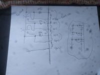
Check001.jpg

So we take the time to draw it ourselves.
We confirm the basics:

* Is there RC filtering on inputs? Yes... a cap on the pins with a resistor out to the noise source, therefor it will act as a LPF, sink off noise, average... the things we want.

* What will happen when I shunt the RC resistor? Who cares... we dont take measurements while discharging and the value of R matters not to the ADC input as it is inline.

* Is this the easiest compromise for the best output? Eh... MAYBE NOT. What if we leave R to do its job but strap a giant mosfet across the output to dump heat and current for faster balancing?

* Meh... do we want to be dealing with tons of heat and issues? I thinks not. I will just be aggressive with the balancing algorithm and it WILL BE FINE>

-methods
 
So - still have not had breakfast (I like working under coffee and stress).
Sat on the toilet... went to the store...

Came back with this:

1) A good engineer does not dump 1/2W into a TSSOP
2) Low balance current may not sync up with our overall power scheme - which requires that we sleep 99% of the time
3) Laying 12 more parts on the board at time of build... is a one time event.
4) If we add 12pcs of 10ohm mosfet in a large package... we can bump balance currents by an order of magnitude
5) We can keep the TSSOP cool - or at least minimize the thermal swings
6) The most common case will be 11 channels ON... and this is demonstrated in thermal rise in one of the graphs
7) We can directly drive an external digital gate fet - but we need to be a bit careful. We can drop the gate resistor and possibly the shunt resistor
8) We could drop our RC resistor down to something like 10ohms and still get some filtering - probably enough
9) Heuristics to detect charge state are expensive in overall quiescent current.

We want to minimize overall quiescent current and up time while maximizing balance power
No where in the requirements does it say we must "minimize parts count or build time" (so far)

Now for Breakfast.
Cap'n Crunch was on sale for $0.10/oz

-methods
 
In case anyone is reading... and I skipped a step....

The internal mosfets of the LTC chip are going to be about 10-14 ohms
We are dumping the lions share of the heat outside the chip
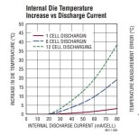
We will still see 60mA^2*14ohms x 12 inside, which equals apx 50mW * 12... which is over HALF A WATT

So - what is half a watt?

DieTemp.jpg

Linear Technology is your BEST FRIEND

Companies like ... Maxim are NOT YOUR FRIEND if they advertise clever capabilities without showing you EXACTLY what the price you will pay is... in terms of thermal, % error, etc... so that you can make an informed engineering decision.

So - what is a 20C increase (INCREASE) in die temp?
Well... its additive to the rest of the increase
It is a 70F increase in temp
It is ... not to be ignored if we want to build reliability without calculating every single little bit of minutia.

If heat can be avoided - DO SO.
Never consider gluing a heat sink to the back of a chip :idea:

-methods
 
We just received a cash injection to the tune of $500. It will first be directed to the smart power switching (be that bidirectional mosfet, contactor, or both)

Ok... time to quick dicking around and build this out.
Enough time has been spent pondering.

I found my old Eagle layouts from V1, V2, V3, V4... so I can skip a step or three if I use the same parts I used before.
Found my old build kit - so I have enough parts on hand to build out 70% of a board

Final Decision on this part of the project is how much balance current to add... and where that heat will go.
I can always under-pump the balance lines to PWM them down to something tolerable... so... leaning toward going big.

Excited.

Moving over to the power switch. This is on simmer.

-methods
 
Good questions

I am still going on the assumption that I will have to build by hand.
I am not certain I will seed enough cash to do a production at a board house.
So - splitting the difference.

I have turned down the "knob" (or weight) on component count.
I justified this by calling it a "one time cost" on the assumption that this fails to make it to production and I just "build a few for friends and investors"

I tabled the Arduino idea once I saw you had a handle on it.
As for the LTC... omg... it looks SUPER COMPLICATED.

That said - I love Linear Technology and I want to support them.
I see that they have been purchased by Analog Devices.
I am certain they will support this chip long enough.
If it goes out of production - I will modify the design to support "old stock" on the design variants.

K - I am juggling 8 trajectories.
Back to Balance Currents

Every channel will get an R and a C
I no longer think it is a good idea to balance at 60mA and heat up the TSSOP with a watt.

I am looking at adding a third component per channel
A high ON resistance mosfet - directly driven off of S(n) and right across the cell
Looking at something like 10ohms... for a 400mA peak balance current
Plan is to characterize... or directly measure temp... and offer variable balance current:

400mA (or so) until things get too hot
Then blipping back to 100mA or whatever current I can sustain with X number of cells discharging into a potted assembly on a 120F day.
So - no actual discharge resistor - just a big body fet. Not sure about it yet... and hard to share all that heat when each must be isolated...
Not much thermal mass to sink into. Cost on parts will be high.

There will be No Fans
There will be no tower resistors poking out of the potting
There will be no aluminum heat sink ... I dont think...

I am hoping to cheat-heat for quick balancing of small packs in time slices.
Fallback is super slow balancing overnight.

I think I could do a lot by using thermals through the PCB to a semi-flat surface
Insulate semi-flat surface with something thermally conductive but more compliant than Kapton
Maybe one of those grey strips they use in the infineon controllers
Back that with a bar of aluminum or some other chunk of metal

Heat builds up fast. I dont like doing the math because it shows that it wont work well :lol:

Maybe I find a heat sink on Amazon... some cheap extruded aluminum
Maybe I put the whole thing in an extruded aluminum case with kissing contact of fastened contact

I am going to be built into a battery... so best to assume I have to eat my heat with time.

-methods
 
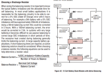
Calculation of heat buildup with balance currents

balanceCurrent.png

Sort of an advertisement for active balancing.
Active balancing of course makes sense... but I am not convinced that it is mature enough yet.

I did a quick review - gets expensive quick.

If I did active balance... it would probably look like a Ghetto party
Nchannel Fet on each cell
Enabling 5Vto12V 1kv isolator DC-DC on each cell when desired
Stacking into 12 or 28 diode paralleled ... (since they are isolated we can parallel them)
Then Boosted back up to full pack voltage to recycle
Lose only perhaps 30% of the balance to heat, rest goes back into the pack

Yea... not as good as shuttling paradigms

Distraction
Back on topic :mrgreen:

-methods
 
So a 50Ah battery

5% SOC fail equates to 2.5Ah of imbalance
500mA of balance current need to correct in 5 hours
1A of balance needed to correct in 2.5 hours

Wow... seems really aggressive.

Maybe Steve and I were right all those years we argued for aggressive balance current.
People in the industry have designed around super low balance currents - even for very large packs
The Entire Zero Monolith (4 bricks) balances on only one BMS and it is a tiny amount of current under a centimeter of potting.

I guess it works when you have PERFECT cells.

Lets see how rad it works when the cells are 3 years old.
(as all cells will be in the future when we start up-cycling)

Cell Imbalance is a reality that designers of the past 5 years have refused to recognize for the inconvenience it presents.
The truth is inevitable and unavoidable.
Reference Tool Packs of all sorts... that degrade in performance. Just open them up and check the cells.

Argument from Battery designers: Once cells are that imbalanced the actual capacity will be diminished so further balancing does no good.
(good point)

But we should be able to match all the cells at HVC and keep them synchronized to the first LVC
Otherwise we start bounding in top and bottom with the highest and lowest cells
Unacceptable performance follows.

-methods
 
Seems to me that "slow balancing" should be adequate. Less heat buildup, less cost, etc. Spending a lot to balance faster doesn't have a lot of return on investment. This has an impact on the design, balancing needs to be able to go on, so it needs to be low power. Actually, with multi micro designs the micro consumption can be part of the balance current, the cells that have reached the target can shut down, possibly, or drop into a very low power mode as needed to support the communications infrastructure.

This is similar to the "supercharger" mentality. For most of us, vehicles sit for 90% of the time and there is zero need for super-fast charging (or balancing). The tremendous idle time can be used for charging and balancing slowly. Fast charging is fine, it just needs to stop before overfilling the weaker cells. But if they are already balanced from all the slow charging and balancing, they can do a few fast cycles without limiting the full charge capacity much. Fast charging usually has to stop well before 100% anyway due to cell temperature rise.
 
Back
Top