LTC6811 Implementation Thread

Starting the PCB layout..... NOW (3:20PDT)

I will leave that section for last and focus first on laying out the power handling area.

The argument to slow balance above either assumes a bike sits on charge for extended periods (which most people dont out of justified fear I suspect) or that a more complex system is in place.
Agreed that tool packs sit on the charger and would work
Agreed that I would like to rely on long 12hr balancing sessions
Agreed that I store most of my packs fully charged and would be happy to leave them on a "trickle charger" (even tho we dont use that term anymore)

We will see when that time comes.
I am just going to wing out whatever wings out unless someone else does the math.

-methods
 
Might be cool to offer a wireless version in addition to CAN and/or SPI in the future

see: http://www.edn.com/design/power-management/4443071/3/Wireless-battery-management-systems-highlight-industry-s-drive-for-higher-reliability.

you don't have to work on it now just leave provisions
 
Not sure the pack needs to be charging to balance. It can balance 24 hours a day if necessary.

The primary imbalancing mechanism is what?

Lack of balance is equivalent to energy leakage. If the pack is unbalanced that much energy is leaking, and lost. If it is leaking 1AH per day, is that a useful pack?

60 mA of balancing current can balance 1.4 amp hours per day. It would take 60 mA of continuous leakage to cause that much imbalance. Are packs that bad? They would be dead and ruined in a few days of sitting.

If the pack is off balance by 1 AH then that just stops charging 1 AH early. One approach to balancing - start when charging at some voltage level less than HVC and continue until it is done. Shut off the charger at HVC. If the charger is connected it can restart the charging periodically to stay near fully charged. There are a few more states - could be charging, actually charging, balancing and charging, just balancing, idle, discharging/regen. Once balancing stops it doesn't restart unless charging occurs again. Also have a threshold below which balancing stops? Give it a band to work in near the top.

Doing balancing quickly creates a heat problem in the BMS. which is probably in the battery. Not good.

If the balancing runs each time the battery is charged then how far out will the battery get?

Instead of doing balance Fast, do it Smart. Doing it Fast creates problems and unnecessary expense.

Another BMS function I'd like to see is after a period of time the BMS should discharge the pack to standby voltage. Such as after a week it discharges the pack to 70% (or some level) to preserve the life of the pack.

If a pack is sitting for a long time and starts to get below a low threshold (say 30%) there should be an alarm, like a smoke alarm. Very low power, squeak periodically or some such. The BMS can wake up once a day to check for this. WHen the pack gets low enough it should stop using any energy, trying to preserve the battery as best it can.

Perhaps have a pushbutton to get battery status with an LED blink code. Simple, cheap.
 
Those are good Requirement drivers.

Thanks Alan.

To achieve a scheme like that - our quiescent current will need to be sufficiently low enough to "stay on".
The Mosfet Only section of the BMS (125V 80A continuous) will run for under 10uA average draw
I can meet requirements with that, and create a state called "Idle Balancing"

In the case where users want to exceed 80A continuous, or burst into the 100's of amps... the 2W contactor draw starts to really impact things.
I do not want a situation where a pack is sitting with the contactor closed at any time it is not being actively used.

The cells can of course balance with the contactor open... but what I am starting to see... is a requirement to have separate Charge and Discharge lines.
I really wanted to "keep it simple" and just have "Two posts, positive and negative"... but this does not really scale to higher power.
As soon as a Contactor is needed... we start needing a bootstrap and dead man.

For regulation purposes... I am still debating on whether the pack needs to "reset in the open state" - with no charge on the terminals...
Or if there is an application that allows for hot terminals at all times.... as in a situation where the pack is built into something.

It sounds like I need to revisit requirements at a high level before doing any more development.

Off the top of my head....
I would like to break it up into MUST and SHOULD

1) The pack must have the ability to terminate a charge in the case that any cell breaches HVC
2) The pack must have the ability to terminate discharge in the case that any cell breaches LVC
3) The pack must not self discharge at a rate greater than XXuA while at or near LVC

4) The BMS must work for cell configurations from 4S to 28S - with minor changes
5) The pack must have the ability to operate without an external contactor, from 9V to 125V, @ 80A continuous
6) The pack must be able to support a contactor for higher discharge applications in the range of 81A to 800A.

7) The pack must have programmable hysteresis around all opening and closing of the mosfets/contactor
8) The pack must have provisions for precharging - either through PWM (for mosfet only) or via resistor (for contactor use)

9) The pack should open in the case that the output terminals are shorted. Within XXXXuS at a current greater than YYY.
10) The pack should rest in the OPEN or safe condition or should have some provision to "safe it"

11) The pack should be able to keep any group of "salvage cells" in balance...
12) The pack must be able to balance at a minimum of 60mA continuous

13) The pack should have a CAN port, even if unimplemented
14) The pack should have a BlueTooth port for communicating with Android devices

15) The BMS must have provisions for bootloading - possibly over BlueTooth (but that is dangerous lol)

16) The pack must have provisions for indicating state of health, without use of a smart phone
17) The pack should have a display which is triggered by a momentary shorting of two IP67 plugged wires

18) The pack should have a fast, high power state for "datalogging"
19) If datalogging becomes a requirement, the pack must measure bi-directional current accurate to ~1A and up to peak output (swappable sensor)
20) If datalogging, the pack shall capture one complete sample of all measurements 5 times a second
21) If datalogging, there must be cell voltages, cell temperatures, current, state of system

22) The BMS must be IP67 rated or on the way there
23) The BMS must be slim and suitable for building directly into the battery
24) The LTC section should not be distributed without the Smart Switch section

On the subject of Physical Ports...

It is preferred that the pack have two primary terminals which can be used for Charging or Discharging interchangeably... such that regen is equivalent to charging.
It is acceptable if the pack has a clearly marked "charge port" (of visible lower current handling), separate from the primary discharge lines, tho this invites failure
(Unless I run back to back fets... ON BOTH... one can charge through the body diode of the mains and discharge through the body diode of the charge lines.

25) The BMS shall not be retarded expensive....

My purpose for this:

a) I want to leave a 4S battery in my car and use it as a starter and ACC battery
b) I want to have a jump-start kit in my trunk that does not cause wicked sparks until I want it to
c) I want a 4S to 8S battery for powering trolling motors on a kayak (wet saltwater conditions)
d) I want a 12S to 24S battery that does a damn good job of running an Ebike
c) I want a BMS that I can slap on a Zero 28S pack for use at 1000 amps

ISSUE) Zero packs are potted with RTD's inside... will need to allow for those to "come in" to the LTC chips as opposed to having them built in.

ISSUE) I only want to interface with packs that have self resetting fuses on the balance taps. Even if they are at 8A... I dont want to see any burnt spaghetti.

-methods
 
I did not address details around:

* Hot swapping batteries (matching batteries in parallel via CAN interaction)

* Details around Boot Strapping and Dead Man timers

* Details around external inputs to cause the contactor or mosfet to Open or Close

* Details around the state machine, how programmable it should be, what parts are MUST and what parts can be modified.

Major Scope Creep...
The idea was just to KEEP IT SIMPLE
It has gotten complicated :?

-methods
 
The pack DOES NOT need to rest in the open state
This can be handled by careful connector selection that blocks human access to the high voltage
 
To be solved:

For any currents below 80A I can directly manage charge and discharge current, including short circuit protection.
(Direct control via mosfets)

For currents over 80A.. where the contactor becomes part of the system, quickly detecting short circuit and monitoring bidirectional current becomes a Power Issue.

In a perfect world:
I would drop the mosfets completely
I would run a range of contactors - small to large
I would intelligently manage the 2W contactor coil expense
I would have provisions for boot-strapping the system into a charge or discharge ready state
I would monitor current through a (does not exist) supper efficient bi-directional hall sensor
I would monitor current through a (does not exist) physical shunt that could read 1A to 1000A (10bit ADC)
I would not have a bunch of opamps and biasing circuits and clutter all over the board... I dont want to make another clutter-board
Parts would be interchangeable with ease based on power requirements with a quick Android or PC flash

And... this brings me back to just punting the whole mosfet thing right across the field into the bushes... and focusing again... on how efficiently we could run a contactor.
The math again:

Common 4S pack:
4S 10Ah, 148Wh
2W for the contactor... so if left on at a full charge we get 74 hours or run time
In perspective... common draw would be 30A, 444W, so 2W, so less than 1% loss

This is about worst case

Assuming the contactor drive is SMART... and has a clever way to turn on (boot strap switch) and a reliable timer to turn off.. (but NEVER while in use)... I could basically drop 90% of the complexity and unreliability in this design.

I could take the mosfet drive work we have done... and apply that to a PWM Contactor Drive... such that we can run 12V, 24V, 48V, and 120V contactor coils
I could make the contactor drive ROCK SOLID.... like... 400X margin on voltage and current... such that all else will fail before the contactor mosfet does

For PreCharge... we can watch the open side of the contactor... and either EEEP a PWM signal over there... or use a good ol giant resistor for the job

Since I am about to take a very long drive... I am going to pause the current design effort, assume that there will be no direct mosfet control over anything, and pivot over to: "Assume you must use a contactor for all power levels"... and see what I come up with for the above listed issues.

* I want to avoid PWM precharging... it just adds unnecessary risk and complexity
* If we boot-strap with a resistor it needs to have a timer on it to open in the case that Boot Strap is held down
* We need to really think about applications where the battery is built int... and how the need for Boot Strap impacts the end user and system integrator

Now... to pack my camping gear.

We are getting paid for this... so we are going to deliver... lets make it as awesome as humanly possible.
Ok - before I pack camping gear... I will research the latest on coil economizers.

-methods
 
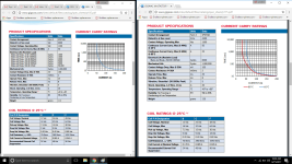
Gigavac:

App note around super heavy duty contactors
Coil power down to <2W
http://www.gigavac.com/sites/default/files/AN-016-Driving-Contactors-w-External-PWM.pdf

Those contactors are out of the league of where I want to be
Principles are the same tho... dual coil... current feedback... PWM...

I DO NOT want to get into the situation where the BMS (like the Sevcon) requires complicated programming and tuning to meet customer coil requirements.
I DO NOT want to settle on a coil that is 12V... and requires PWM from up to 125V... to run... this will cause unreliability
I DO want to allow users to employ a 12V, 24V, 48V, or 120V coil for direct battery attachment with an economizer built into the coil or added to the coil but not part of the BMS

Now... I could (COULD) kick down pack voltage in the range of 12V to 125V to a 12V buss capable of coil driving...
That was suggested early on and I *always* come back to that.
Some onboard caps... or even an onboard battery... can handle the punch needed to close the contactor.
After that all that is needed is holding current... which is far less than closing current.

-methods
 
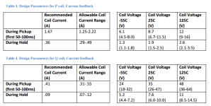
This charge shows P and Q coils in feedback (constant current) mode

P = 12V coil
Q = 48V coil

12Vand48V coils.png

Quick math shows that with both Q and P coils can be held across temperature at less than 1W
Ok... a 50% improvement
I want to see better.

BUT THEN... this is for... eh... like 300A contactors capable of bursting 1000A :shock:

Off to research high voltage low current contactors in combination with an economizer - built or procured

-methods
 
Which... brings us back to my original design...

Around a LATCHING RELAY

-methods

GV series... latching... off the list for being too large and not immediately commercially available
http://www.gigavac.com/sites/default/files/catalog/spec_sheet/gvL144.pdf
(I try to stick with only those parts which can be had at places other than direct from manufacturer)

GXL series... latching... off the list for availability
http://www.gigavac.com/sites/default/files/catalog/spec_sheet/gxl14.pdf

MXL Series... latching
http://www.gigavac.com/sites/default/files/catalog/spec_sheet/mxl14.pdf

Note... when I kick something off the list for "availability"... it is less about whether it can be had... and more about economy of scale. We want to use parts that other people are using so that we can share in production savings, find them in the aftermarket, and not get stuck having to pay and wait for a production run. Its just good business that you learn after being the spear head for an unpopular product line.
 
And...

What if we turn logic upside down and run a NORMALLY CLOSED contactor eh???
Hrm..... sounds like a bad idea...

During charge... we have the charge current to pay for the work of keeping it open....
During discharge... meh... thats an eat you alive situaiton... but...
There may be ways around it.

Two contactors in series or parallel (Throwing caution to the wind here... forgetting logic and cost and complexity and size - pure brainstorm to bound problem and eliminate distraction)

It is not a NON STARTER... just... a real HARD STARTER
Like a rusty old 235 straight 6 with a leaky carb.

-methods
 
And in case it looks like I am off in the weeds... the line of spock logic is:

"Since we have already agreed that we could rely solely on a mosfet for direct control of charge and discharge... we can equally rely on a circuit capable of Un-Latching a latching relay"

This was not always the case during debate.
I am confident that I could store a charge and guarantee the ability to "blow open" at least one time and until a user intervenes.

I will check on pricing in 10's

-methods
 
Called Gigavac...

Oh this is exciting...

So here is the breakdown

GV series is aimed at Automotive serial production
GX series is good for low contact resistance (copper)
MX is the rough and tumble for opening and closing under loads

All of those flavors sell for about $100 in NO and maybe $150ish for latching
All large, all major overkill

BUT... if we look over at the P series.... which I have been drooling over...

We can run a 1.2KV 50A...
A P105 or P115...
For about $35

We can get coil current down to around half a watt with a PWM setup
Ok... a 4X improvement in waste power and much closer to what we want to do

As far as running them... we would never try parallel...

So for folks looking to run 50A continuous or less... a P-Series with 1/2 watt burn rate
For folks looking to run greater than 50A and upward to 1000A burst we pay the price of bulk, triple cost, and double burn rate

1/2W.. I will now research the P series in detail
Work the PWM math, look at coil flavors

They have them in stock and ready to ship

Meh Meh Meh
Round and round trying to jump the gap on the solvable but totally unsolvable problem

So easy to make a specific application
So much detail in trying to span 12V to 120V and 12A to 1200A

I can do it.
It shall be done...
It will be reliable
It wont kill batteries
It will be rad

And - now I remember why I used to have 4 monitors while doing this sort of workgoingForit.png


-method
 
To run a 12V standard or to match coil to pack is the question

Settling on a 12V standard will mean any contactor can plug and play.
It will mean some losses and risk in our DC-DC and a robust DC to DC or an energy storage solution like a bank of caps - but still enough to power continuous

12V standard:
7.5V to 16V acceptable
70 ohms
170mA

Nominal
Max

Pick-up max - 7.5V guaranteed to go from closed to open
Drop out max - 5V wont close it, but also wont pop open if held above 5V
Drop out min - will absolutely close around 0V (yea, duh :wink: )

So we have to hit it with 7.5V to 16V then we can PWM back to ... 5V or better
5V/70ohms = 71mA or 357mW hold

12V/70ohms = 171mA to drive or 2 watts

On the other hand... if we play mix and match...

7.5V to 16V
15V to 32V
30V to 64V

This translates to

3S to 4S pushing it on the high end
5S to 8S pushing it on the high end
10S to 16S pushing it on the high end

I dont like all that fuss... that is not in line with the directive to make a one size fits all BMS for use across all my projects.

So - if it is to be a Contactor.. it shall be a 12V contactor

We will not PWM arbitrary voltage to try and drive it, we will need a dedicated DC-DC.

DC-DC power would need to be able to source 1/2watt continuous and 2W peak at 12V for a P series
For a heavy duty series (say a GX14) it would be 3.9A to .23A, so 50W for 75ms then 2.8W continuous (DOUBLE ACK but worst case)
For an input range of 4S (12V) to 30S (126V) we are looking at:

Ah boy thats a tough one to solve.
We would be getting into stored energy and lockouts. A cap bank which can charge slow and blast 4A for 100mS ... and still need a steady 3W...

Which puts us back on use case tuned coils

P series - run them all at 12V
GX series - run them at matching voltages

Barf. I am quickly loosing interest in supporting the 28S packs
They make a 116V contactor just for those packs...

Maybe I punt on the idea of supporting such high voltage.

Camping... I want to be camping... :D

-methods
 
Please do not make me implement a PWM circuit that can take 12V to 126V and PWM out a 12V 4A signal
I know that would be an excellent exercise...
Just a nice big coil, a nice big pair of fets, a nice LTC control chip, and a nice 300 hours letting smoke out in the lab
Its already been done by guys better than me

Thats not my path.... :shock:

I could do it... but am not wanting to.

Sevcon does it... but not awesome.
I mean... I could just straight up PWM signal into the coil, set up feedback, filter the feedback, and converge.

Smoke at unforeseen times... circuits that totally work... then dont.
NOOOOOOOOO!

-methods
 
So this is where we "real" it in with a reality check

(thats a patented Santa Cruz term I learned from guys who poop under bridges and eat garbage... they know where the rubber hits the road)

50 Amps....

at 4S that means 740W CONTINUOUS with the ability to burst to 200A for 10 seconds, or 3KW
Call it
1hp continuous with 3hp burst

Thats pretty respectable for a 12V batter :shock:
Breaking that kind of burst current would be... a destructive test

At a more healthy voltage like 24S or a round 100V
Call it
5hp continuous with a 20hp 10 second burst

And 2.5hp to 10hp on 50V (ebike standard)... pretty stout

We wont run the math on the big contactors. Those are Motorcycle status and the batteries are large enough to eat heavy coil currents

Applications:
A pair of headlights draw about 100W continuous... we could run 10 headlights out in the bushes
A trolling motor runs probably 30 to 50A... no problem
A car starter can draw hundreds of amps... but I have started many Honda's using long 10AWG cables... even big 5.4L V8's with caution (you cant crank for more than a few seconds)
An Ebike... yea.. I owned a 100V 50A continuous Ebike... thats converging on death machine
A lawn mower? Different range - looking at 24V, 36V.... easy cheesy
A stationary Power supply for an UPS or something similar? Well - 1KW does the trick for most stuff and nearly all products run at under 1.5KW... You really need to step up out of 12V to make power.
Trolling motors come in 12V, 24V, and 36V these days...
What the hell are we going to do with all this power?
Ebikes seem to be the best use case for the "Under 50A continuous" range.

So now I will go look at DC-DC converters again.

-methods
 
Lots to think about. I'm going to fling a few more thoughts out there.

1) I wonder why BMS's switch the raw power to the controller. All that need be switched is the power to the controller logic (and aux loads). The "main raw power for the controller to invert to the motor" doesn't benefit from switching. I'd use a circuit breaker for that line, but don't need contactors or FETs. Make the high current switching an option, most systems don't really need it, or the requirements differ by so much a separate implementation would be appropriate.

Having separate charging input seems like a reasonable optimization. Saves lots of money, size, heat loss, etc.

Things like Bluetooth should (IMHO) be an optional separate layer that isn't part of the core BMS. Can be added. Some sort of basic comms needs to be in the core to facilitate it, then an add-on module handles the display/BT/CANbus/whatever.
 
Alan B said:
Lots to think about. I'm going to fling a few more thoughts out there.

1) I wonder why BMS's switch the raw power to the controller. All that need be switched is the power to the controller logic (and aux loads). The "main raw power for the controller to invert to the motor" doesn't benefit from switching. I'd use a circuit breaker for that line, but don't need contactors or FETs. Make the high current switching an option, most systems don't really need it, or the requirements differ by so much a separate implementation would be appropriate.

Having separate charging input seems like a reasonable optimization. Saves lots of money, size, heat loss, etc.

Things like Bluetooth should (IMHO) be an optional separate layer that isn't part of the core BMS. Can be added. Some sort of basic comms needs to be in the core to facilitate it, then an add-on module handles the display/BT/CANbus/whatever.


Because the BMS should function independently in case of controller component failure, and your assumption also includes integrated controller / bms design
It also needs to protect against short circuit and other safety issues, ideally HV should be isolated within the original battery enclosure.

Sure, the inverter itself can even measure battery temperature, voltage, and shut down proving basic protection functionality...
But if some of the inverter transisters fail closed, or there is physical damage that leads to a short, or a charger is connect that will overvolt - the BMS exists to isolate the energy source and protect the cells seperatly from external sources.
This is especially important for Diy / ebike targeted design as folks are more likely to do unpredictable things and make mistakes with their ebike setup
 
You make some good points, but we need new thinking to avoid the BMS problems that we continually have with this old philosophy. There are already plenty of BMS's made this way (that are frequently expensive, unreliable and bulky and don't handle adequate current for stronger ebikes).

I think a commercially approved circuit breaker is far better than a BMs at providing reliable short protection, and for a significantly lower cost.

Most BMS's do not provide enough current capacity, using FETs for that switching is a very expensive and unreliable way to do it, and essentially redundant since the controller is already doing that with FETs. We are trying to keep costs down while making a system that meets requirements.

Circuit breakers also meet the requirements for safely working on, since they can be locked out physically. BMS's don't provide that capability. For truly isolating power, a switch, breaker or connector is required. A FET is not enough. The Fire Department doesn't even trust these on EVs, they use big wire cutters. :)
 
I have held Alan's approach for a number of years. When I pondered on this a while ago, trying to envelop the problems in a "systems approach" I too ended up with relying on the main power FETs in the controller for isolation, and sending logic signals to disconnect. I.E. dropping the "permissive" for the controller to operate.

I likened this to our automobile starter system, with only a contactor between the lead acid battery and the starter. We relied upon that part to both start the car and isolate the starter from run away.

However, I think the current state of controllers are not quite at that 99.99% reliability level. So I thought we needed a new component, a deadman contactor, that would isolate everything downstream from the battery under an indicated major fault. I doodled some of that design... it was a manual reset to Normally Closed device, with a kick solenoid to unlatch it to the Open position. I did not find a commercial device at the time, but with solid model printing and scavenging parts from contactors, thought a design could be done. Think of it as an remotely "fired" circuit breaker.

I know this is out of scope for this effort, but thought I would put it here to document the concept, and perhaps someone will be motivated to develop such a device in the future.
 
We have used remote trip circuit breakers, they trip with a 24V signal, and have to be manually reset.

Power Supplies are commonly protected against outputting overvoltage with SCRs that short the output terminals when OV triggers them.

Just trying to think of new approaches to this old problem.

Thanks for the good thoughts!

The "system" needs to have various features and properties. Trying to pack them all into the BMS may not be the most effective approach.
 
Alan B said:
We have used remote trip circuit breakers, they trip with a 24V signal, and have to be manually reset.

Power Supplies are commonly protected against outputting overvoltage with SCRs that short the output terminals when OV triggers them.

Just trying to think of new approaches to this old problem.

Thanks for the good thoughts!

The "system" needs to have various features and properties. Trying to pack them all into the BMS may not be the most effective approach.


I fully understand your arguments and even once prescribed to all of them at one point - but I think you suffer from lack of practical implementation

--A deadman's circuit breaker.
It's a good idea, but a circuit breaker is larger and more expensive then 2-4 mosfets for the same current flow.

Keep in mind we are protecting against
-overvoltge
-undervoltage
-overcurrent
-prevent charging when cells are too cold.
-overtemperature
-permanent disablement when something happens that signals a cell failure or an event that may lead to cell damage / fire in the future?

You'd have to do all of these with your remote circuit breaker - and then how do you support it when 30% of your 1000 users trip it for various issues within the first 3 months?
And the circuit breaker is still more expensive and much larger then a few mosfets.

Keep in mind Tesla still uses:
-Inverter/MCU that will shut things down when battery voltage is too low/too high
-TWO contactors in series for the pack
-SEPERATE contactors for the charge circuit
-A pack fuse
-Another fuse for the motor DC link
-FInally, a BMS that monitors everything and will signal shutdown the the inverter, and BOTH contactors in case of the simplest fault.

These things are all in series, for redundancy..
And this is from a company that tries to push the status quo for simplicity/cost - for example - they fought to remove the parking brake from the drive unit to reduce weight/cost - something no other manufacturer has done yet.
 
Mosfets alone even worry me, Since they can fail shorted.
Maybe some sort of logic/circuit that can detect if the mosfets have failed shorted would be worth adding.
 
I thought we were having a good technical discussion here, but is it devolving to borderline personal attacks already?. How does that add value to the conversation??

System requirements are not met by FETs alone, once there is a circuit breaker there is no need to pass main system current through FETS AGAIN. Monitoring FETs? Breaks KISS principle. When it detects FETs are shorted, what does it do then?? Think outside the box. There are plenty of standard (inside the box) BMS designs out there already. No need to make another one like that. Waste of time, actually. We need new thinking here. One or two FETs are not enough for the higher power ebikes. You would need eight just to be equivalent to a 24 FET controller for a two port design (no separate charge port), and more if you didn't want to have a heatsink. If you want redundancy then double the FET count again. Since safety and equipment protection demand features of a circuit breaker, then why bother putting main current through FETs? What requirement drives that? Is it worth the cost/complexity increase??

The solar market has given us DC circuit breakers that are cheaper and more reliable than the end user cost of a similar FET module. Plus the FET module would not meet the requirements that the breaker meets, including UL listing, arc breaking, etc.

If we cut controller and accessory power (with a small FET since the currents are not that high), the controller can't continue to operate.

The breaker protects against overcurrent and shorts in controller FETs with both magnetic and thermal sensing.

HVC cuts the charge port current

LVC cuts the controller/accessory power.

If other protections, such as temperatures of battery, motor, controller, etc can also cut controller/accessory power.
 
Alan B said:
I thought we were having a good technical discussion here, but is it devolving to borderline personal attacks already?. How does that add value to the conversation??

System requirements are not met by FETs alone, once there is a circuit breaker there is no need to pass main system current through FETS AGAIN. Monitoring FETs? Breaks KISS principle. When it detects FETs are shorted, what does it do then?? Think outside the box. There are plenty of standard (inside the box) BMS designs out there already. No need to make another one like that. Waste of time, actually. We need new thinking here. One or two FETs are not enough for the higher power ebikes. You would need eight just to be equivalent to a 24 FET controller for a two port design (no separate charge port), and more if you didn't want to have a heatsink. If you want redundancy then double the FET count again. Since safety and equipment protection demand features of a circuit breaker, then why bother putting main current through FETs? What requirement drives that? Is it worth the cost/complexity increase??

The solar market has given us DC circuit breakers that are cheaper and more reliable than the end user cost of a similar FET module. Plus the FET module would not meet the requirements that the breaker meets, including UL listing, arc breaking, etc.

If we cut controller and accessory power (with a small FET since the currents are not that high), the controller can't continue to operate.

The breaker protects against overcurrent and shorts in controller FETs with both magnetic and thermal sensing.

HVC cuts the charge port current

LVC cuts the controller/accessory power.

If other protections, such as temperatures of battery, motor, controller, etc can also cut controller/accessory power.

I did not intend any of my post to be anything remotely like a personal attack, and I am sorry if you see it so. Could you point out where ??
 
Back
Top