LTC6811 Implementation Thread

Alan thanks! Can't believe I missed "remote operated circuit breaker" ... but I did :oops: Starting to look at them, and found the carling remote module add on to the C series. I have used C series breakers before on some designs and never knew there was a remote module.

This is interesting as it is available (but says: custom designed remote operated motor module) and the breaker and hydraulic module would each be about the size of a 1/2 pack of playing cards. More on it here: http://www.carlingtech.com/hm-cb-c-series-remote Can get 100A at 80 VDC and 60A @ 125 VDC Think something could be made with a hobby servo and a rated breaker... but that is another development project, not KISS and not off the shelf.

EDIT: Off the shelf remote trip solar circuit breaker for $100, but its big. https://www.solar-electric.com/midnite-solar-mnedc250rt-remote-trip-circuit-breaker.html

Don't want to derail methods thread, so I'll leave it at that.
 
Removing logic power from the controller is pretty reliable, though it doesn't protect against shorted controller FETs. The breaker should protect against that. At some point the designer must decide what perverse things they are protecting against, there's always something that cannot practically be covered.
 
All good conversation.

I am leaning heavily toward 1200V 50A gas filled contactor.

A major puzzle piece that is missing from the above discussion is:

* Pack quiescent current
* Packs stand alone for systems other than ebikes.

Those two are major driving requirements for me.

I would go Contactor hands down if I could... and a breaker... well... that addresses the coil current draw.
I will pivot my research to DC breakers intended for solar etc.

Thanks for driving requirements guys.
This is still a project without a customer... so we are really just spinning our wheels keeping the rubber warm until someone lays out what they want me to do.

(Which will likely be specific... but I will take the learnings from that and apply it to the general solution)

thanks,
-Patrick
 
Starting with Google search terms like "Solar Breaker"
(as opposed to DC breaker...)

Wow - $11 for a 150V 60A breaker
DC Breaker first https://www.google...com/lib/wind-sun/Q-Series-breakers.pdf]Manual

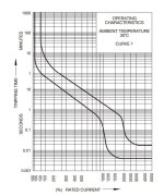
Delay Curve Example (random from datasheet)

DelayCurveExample.jpg

Hmmm... actually looks reasonable for dealing with short circuits of the type I often see (jumper cables slapping together)
Not lightning fast by any means.
I would need to compare response times of fast acting high voltage DC fuses.
The Mosfet switches can turn off pretty quick...

Now - those look interesting, especially for lab setups, test stations, or general use.

Onward to search for similar but with a trigger line that smarts can control
Hopefully open collector (Not possible) or otherwise not requiring 24V AC or DC
Or... at least 12V DC.. as we may end up with a 12V rail.
I dont want to boost a high current 24V rail
Never have liked 24V standard (personal bias)

I am specifying 4S as a hard bottom limit.
I am sticking with a 150V parts rating for absolute max 117V use case.
From that I would like to build a DC-DC buck capable of 100% duty cycle, up to 150V, up to 400mA/2 and capable of 10uA or less sleep current.

That should be able to punch open a breaker or open a standard relay

As for short circuit protection.... no idea what the current regulations state... but a Contactor blowing open + a properly rated fuse will have to be enough.

-methods
 
At $10 bucks for a breaker, it might be worth the design effort to add a solenoid and make it remote trip. Some type of 3D printed attachment. I think there would be a saleable product there. Pick a good solar breaker brand, small and reliable that is the same physical size for various amperage, then the kick solenoid would be a universal addition.

Some remote trip say 15 to 20 in-lbs needed for remote trip function. Guess they are called "shunt trip" attachment. From page 11 and 12 https://www.google.com/url?sa=t&rct=j&q=&esrc=s&source=web&cd=3&ved=0ahUKEwjZg7_xm8_UAhVFNz4KHbFGDGMQFghbMAI&url=http%3A%2F%2Fwww.eaton.com%2Fecm%2Fidcplg%3FIdcService%3DGET_FILE%26RevisionSelectionMethod%3DLatestReleased%26Rendition%3DPrimary%26dDocName%3DTB01200003E&usg=AFQjCNEBAHSwgFoebXBHhSCZCqC9qnm0BA&sig2=Uux-1eFhqHdZxuUZHTQY5A&cad=rja
Shunt Trip
The shunt trip provides remote controlled
tripping of the circuit breaker. The shunt
trip consists of an intermittent rated
solenoid with a tripping plunger and
a cutoff switch assembled to a plug-in
module. When required for ground
fault protection applications, certain
AC rated shunt trips are suitable for
operation at 55% of rated voltage.
Available in most AC and DC voltages.
Note: Approximate unlatching time—
6 milliseconds. Approximate total
circuit breaker contact opening time—
18 milliseconds. Endurance—4000 electrical
operations plus 1000 mechanical operations.
 
Sitting in another airport parking garage... Absorbing the delay of margin.


Wow - that's out of the box Bigmoose.

We make our own reliable one way latching contactor that has zero risk of going into oscillation and requires human intent to reset. (pay attention guys... that part is really smart... Even from a lawyers perspective)

It at first seems clunky... But that is how all new COTS parts start. Some Bigmoose in a lab somewhere cobbled it together from epoxy and old brackets.

Well... Mark over at Earth Star Electric Planes kindly made a 3D printer available for us to experiment with. I have been looking for a productive first project. That sounds like it.

Solenoids are simple and useful in all sorts of safety applications. They can be had for dirt cheap ... all th way to super reliable. Large and small... They require nearly no power under the curve and are a great example of the most basic but practical Electrical Engineering in practice.

Who would have thought that winding a conductor could directly induce force... Imagine the first people who discovered this... Pure magic... When combined with the first chemical energy.

Anyway... The solenoid can be NC where a "dead man voltage" has to hold it open... Or it can be NO where we assure we have enough isolated stored energy, along with a robust triggering mechanism... And that would package up nice as an accessory which improves safety.

Triggers... Like
LVC
HVC
Temperature
Excessive impulse current
Deadman timer
Heartbeat latch

Any of these can trigger a device like this on a different reliability accounting than the BMS.

So... Even if our BMS fails... Our safety does not.

The final interlock on a safety system must converge on 99.99
If we can accomplish this... Then we can absorb more risk in upstream circuits.

"Just avoid fire please"

-methods
 
And here I was hoping you would choose a pyrotechnic squib in lieu of a solenoid... :mrgreen: Some fun irrelevant reading: https://ntrs.nasa.gov/archive/nasa/casi.ntrs.nasa.gov/19890005798.pdf

Seriously though I would consider a circuit variant on a basic principal that we used to "fire" the NASA Std Initiator above. Basically we charged a capacitor and discharged it through the NSI to blow the bridge wire and initiate the discharge. So in our application I would charge a suitably sized capacitor from the main battery voltage through an isolation diode so that it was charged and not drown down by the bus going south. Then to "fire" or "trigger" a 5V signal to the gate of a low gate voltage FET would fire it through the solenoid. One cap, one pulse, mains off! Cap value may need to be dependent upon the mains (battery) voltage. Lower voltage higher uF.
 
Actually I was going to implement a thermal battery that lights off at the first indication of over-current :mrgreen:
Should only take a few minutes to kick open.

-methods
 
I do have 2 kilo's of Potassium Chlorate (not per) that I produced using electrolysis in my chemistry days.
Our plan is to mix it with sugar to make marshmallow smoke for 4th of July... Back in Livermore I once added a few drips of Sulfuric Acid to a 2' length of 1" PVC packed with a finely ground 50-50 mixture. It created WAY more smoke than anticipated.... the street was out of service for at least 10 minutes.

Edit: The original intent of the chlorate was low cost oxygen production. If decomposed it produces large volumes of oxygen, and many industrial processes and machines use this method. It is cheap, easy, and goes back centuries... I never got around to it - so the substance that I had on hand (which is perfectly legal and available, and which I have the laboratory experience to properly manage, store, and transport) was destroyed. I experimented with several methods. Decomposition is the cheapest and easiest... effectively cooking it down to a salt... but I also tried SMD (Sodium metabisulphite - which I had on hand for precipitating gold out of Aqua regia... but which takes a ridiculous amount + HCI or Sulpheric Acid + Sodium Hydroxide to acidify, convert to salt, then baseify and neutralize for proper drain disposal.... anyway... People these days are quick to judge and can not even comprehend how someone could experiment with such things and NOT be an ISIS terrorist :roll: So.. I wasted it through proper destruction methods in order to protect myself from WELL MEANING ALARMISTS. LAME.)

The neighbors were really not too mad as it smelled like sugar. Had it smelled acrid - I probably would have had to deal with the Police.

On topic:

I did a half-ass survey of the solar breaker idea here

I only really looked at one company... found them to be a great bargain... then came to the realization that I think I am going to need programmatic make and break of the primary switch. I do not believe I will be able to meet IP67 in a situation where the user can quickly reset the breaker in the case where it is triggered by an anomaly as opposed to LVC or short circuit.

-methods
 
Ok -

Since I am stressed out over career change, having to drop my son back at his moms, and finances... I am going to just make some decisions and see how it feels.
As CEO, CTO, Head of Marketing, and "Engineer Supreme" of this non-existent and non-paying company...
I declare that the best path forward is to eat the Economized coil current and spec the $35 P115 Contactor

P115BDA
Datasheet

We will take it only in the 12V coil flavor and shift our focus over to building an extremely robust and reliable coil drive and economizer circuit.
That is easy enough... but there should be some nuance around making it super reliable across abnormal environments.
We will build enough margin to drive the biggest contactor on the market.

If we decide that large piece is jammed into the knapsack... well... then the rest of the "knapsack solution" becomes PreCharge.

My vote is to go with a standard Precharge resistor - either mechanically or electrically driven.
My second vote goes to trying to PWM over the gap (meh... so many issues with that)
We will need to probe the open side of the contactor as "standard" now... which will mean a physical wire running out to the post. Perhaps we can incorporate that with a PreCharge circuit that is in some way dummy proofed against wiring backwards.

-methods
 
I've got the battman files I linked to earlier imported and I am going to order a few PCB's and components on his stock design.

There are changes I want to make to the design to fix some minor design issues (like the RTC powered from a single cell)
But I believe the design works overall and want a physical part in my hands so I can start understanding the layout and making code changes.

It would help if a few people wanted a board to help cover costs. That way I can order, say 4-10 PCB's, components - I will solder them myself (reflow oven)

Seems that noone has gotten any boards from raphael yet. I don't know if he is having issues .. or some 2nd thoughts from the email I sent him on my concerns. (he never replied)
But I know the basic design should work okay from his test video's.

Here is raphael's thread:
http://www.electric-skateboard.builders/t/raphael-chang-bms-and-esc/8952/308

Any interest in a copy of his beta boards?


edit: here is a link to the pcb file in Circuit Studio format. https://1drv.ms/u/s!AuqwBZb5n5Jqgr9ojJbV5povL_Mk9Q


(ps, I am really liking circuit studio so far. WAY better then designspark.)
 
ack - did someone actually pull the ol "Draw from the lowest cells" trick?!?!

I am good on boards.
Take lots of pics for us!

-methods
 
methods said:
ack - did someone actually pull the ol "Draw from the lowest cells" trick?!?!

I am good on boards.
Take lots of pics for us!

-methods

Yeah I mentioned it in post on 1st page.

Seems like a common theme with BMS design problems.

1.) power something from a single cell or not have even draw for some reason
2.) too high off/sleep current - drain the whole pack over time
3.) "cool" feature creep (like BT or WiFi or some other crap) that leads to lack of needed features and/or 1.) or 2.)
 
Yep.
I see how it happens too.... Super easy to lose the forest in all the trees.

I am moving forward with the low cost, high quality, Contactor approach
Storage current will be below 10uA

Nobody has really done that yet... perhaps because the P115 did not exist or is not widely known.
If it were latching... it would be a dream come true.
The latching relays cost 5X as much and are 5X the size.

-methods
 
That said I think raphael's battman design has merit. And I've been looking for a starting point for this for over a year now.

-It's got a nice compact layout with all LTC6803 features implemented
-smart design using a modern MCU
-Integrated MCU controlled DC/DC boost so a single pack (up to 12s) can be charged with an external DC supply. Cool feature!

Just needs:
-get rid of the RTC is powered from a single cell
-perhaps change to a STM32L4 design that is lower power and also has internal RTC with ultra low power
-update to LTC6811?
-update layout so external connectors can be used for SPI daisy chain interface
-related firmware development
 
Great - I am glad you found a bone to chew on.
I like picking up on others work as well as starting with a blank page.

I suggest going with the latest LTC design that you possibly can. Linear is a company that improves their designs with time... I have spent a great deal of time reading the 6811 data sheet and they have definitely taken feedback from the field to robustify the chip.

I am still going with the 6811

-methods
 
Recruiters...

I swear half of them are doing the job while asleep! I have wasted so many hours responding to their requests...

I just lined up with the latest cold call. This guy seems pretty quick. Has a test engineer job over in San Jose that pays oK... but would be super easy ... as it is basically what I am the ridiculous master of (LabView Test Stations)

I would love to just crank labview all day. It makes time go in fast forward for me... and the graphical nature of it allows my brain to crank on it while off hours such that when I get started in the morning... the code just squirts out of my mouse like a hose :mrgreen:

-methods
 
I am not particularly enthusiastic about this guy... but here is a PreCharge write-up that is pretty lucid.

http://liionbms.com/php/precharge.php

I am still miffed that he put one of my early BMS devs on his chart but showed only unpopulated boards... as if it were a design that did not go out in the field for test. To be fair - he offered the service of updating the entry... but I never acted on it... so... I suppose he is a good guy :wink:

-methods
 
A good coil driver circuit that works up to 100v is something that could be handy. Lots of circuits around that will take 48v, but once you reach 60v, the choices are very limited. A PWM buck converter topology might be good as you could use the relay coil as the inductor. Just a low power dc-dc buck converter that can handle 48v-100v is nearly impossible to find.

One solution I've seen used in chinese controllers is a variation on the "Black Converter". Google black converter. Designed by a guy named Roman Black.
These are crude circuits with minimum parts count and no integrated circuits. Just transistors, resistors, diodes, caps. All really cheap parts. Not only useful as a coil driver, but there are lots of times you need a 5-15v source for something and don't want to spend a fortune.

For pre-charge circuits, a resistor will work but you should avoid another mechanical relay for it if possible. Relays are big, expensive, heavy, and fail prone.
The constant dv/dt FET circuit works well if properly implemented.
 
I am thinking that I am going to use the output stage circuit I put together for primary output control as the fet driver.
I designed it to run 12V up to 125V - it will just have a back to back pair of surface mount 4115 instead of a bunch paralleled with a heatsink.

It will definitely run any coil in the world and wont blow.

I do not wish to integrate the contactor coil into the DC-DC... tho that is clever.
I will keep that circuit separate and just accept that I need a 12V buss

I may however integrate the DC-DC into the Coil Drive circuit.... to make it a "module".

If I package the Contactor, 150V DC-DC, Drive Mosfets, open collector inputs... I will have a module which could work without the BMS.
One could wire it up, connect it to any pack voltage, and trip it off of any switch, opto, or digital closure.
It would power up NO
Could be latched into NC
Could be latched into NO again

Any "behavior" around timing, heuristics, etc would be back at the BMS... where I need a microcontroller anyway.

I would be tempted to integrate this into the Contactor... but it would just mean two microcontrollers. Thats not a win.

12V and 5V would then come out of the contactor to power the BMS or any Aux devices
Of course then sleep control lines would have to go in...
Meh... individual components vs a monolithic design

The deeper you dig the more complexity is exposed.
Monolithic... I see why folks go that route

Multipin connectors
Water proofing
Enclosures
Noise and isolation
Power handling

All stacks up as you go modular.

-methods
 
Best constructive criticism I have received so far was from Kingjamez.

He pointed out that for a design this complex to be successful I will need to assume that the final product will be assembled by a pick n place machine.
So true...

As I shift back and forth from block diagram architectural to implementation details I tend to make a lot of poor decisions based solely on my personal bias about what it will take to hand-produce the boards. A perfect example is the LTC high side driver chip. Its an ugly tiny part with lots of peripherals. I get it stuck in my head that IF I need one of those I only want to use one... and not two or three.

Now... for hand assembly this is totally correct.
For machine assembly this is totally incorrect.

There is no way I can successfully design this in a robust way if I am worried about parts count. If I need an OpAmp and a chip to supply it opposing voltages... then thats what I need. In and of itself its just a handful of parts and a few minutes of assembly. It complicates the BOM, increases the cost of the BOM, takes a little bit of schematic and layout time (all one time cost)... but once the design is tested and out the door it costs very little to have a good design.

Which brings me to CURRENT SENSING.

We can not get around some sort of hardware based current sensing if we want to detect overcurrent and short circuit for low power.
Its *possible* that I could run an external hall or coil based bidirectional sensor... but I would have to set it up with some sort of threshold detect to interrupt the MCU... and even then it would cost me 15mA to 25mA CONTINUOUS to have this.

I need a "black box" between the mosfets and the MCU that, on its own, monitors actual output current, and blows open the contactor based on hardware tuned time constants and current levels.
Yea... I could make it programmable if I really wanted to get crazy... but basically we have a peak trip current and a period of time that is allowed.
No getting around it if we want to be low power.

Now... It is unclear as to whether we actually need to *measure* our overall system current.
I think we do... and anyone reading our datalog will expect it...
But its expensive!

A proper shunt capable of 500A costs like $25 and requires a specialty chip or opamp and supplies to read it.
An external shunt... well... those can get VERY expensive. The $25 units require stable +/- supply voltage and are sloppy and fussy and burn gobs of current.
The high end units (all in one) are more like $80 or $180 bucks (we are talking bi-directional DC current detection on a reasonable sample rate with accuracy sub 1% on selected range)

My gut instinct is to use a physical shunt on the board and populate it to the current level.
The easiest is to dangle and expensive current monitor.
I dont want to get into having the user mount a shunt + 3 wires for monitoring it + associated circuitry and risk of miss-wiring.

Oh MAN this problem does not scale in an elegant way....

For 100A... even 200A and below... its easy cheesy for Cheap.
Plenty of all in one onboard parts that can give you what you need.

300A... 500A... 800A... it all gets expensive and power hungry

The LTC section and associated microcontroller should be able to be the same for any pack size in series or parallel - it does not care about discharge.

The switching section ... it simply is not something that can cost effectively scale... if you make cost the result of multiplying power consumption times cost in dollars.
Costs too much
Draws too much

For a motorcycle - OK - WHO CARES>>> suck down another 50mA
For a bike... with a 10Ah pack... it matters.

Safety does not scale well either.
With a 100A limit... ok... so we short circuit for a few tens of ms... big deal. Some 10AWG gets warm.
With a 900A limit... ok... uh... thats extreme heating extreme fast even just on interconnects. If you calculate the losses through just 3/8" bolted connections alone your eyes will grow large. The difference between a properly cleaned terminal with grease... and a slightly oxidized terminal dry over time... 900A becomes a very serious issue.

I included the Motorcycle level stuff for a friend... who has great interest in the 28S Zero packs... but that work is not paying into design.
The friends who are paying into this design (2 so far) are interested in Ebike levels. Ebike pricing. Ebike reliability.

Under 150V
Under 100A continuous
Under 300A blip burst
Emphasis on small size
Emphasis on cost relative to high end ebike cost
Emphasis on IP67
Emphasis on dummy proof (as opposed to data-logging and such)
A bike will have a CA... and or a controller.... with a shunt
A bike can run its primary power through a PCB easily
A bike can even run through a direct mosfet final stage
A bike can stand having the system shut down requiring physical reset
A bike can tolerate a boot-strap switch
The PreCharge should actually be the job of the SYSTEM or of the Controller... To take on that job as the BMS is scope creep. Nice... but NOT NEEDED. NOT A REQUIREMENT

It is my job to create PROVISIONS for precharge...
Perhaps hold off on closing until precharge occurs...
But I dont have to go to the trouble of actually DOING the precharge. Not the batteries job. Thats the controllers job or the Systems job
DONE with precharge (Hint... the source of the second LTC high side driver circuit)

Its OK to have 2pcs uController on the board... one lives with the LTC design... one lives with the Switch design... the system should still SPLIT at the interface between the cell level monitoring and the power switching for the reasons listed above. EVEN if it means more power... more complexity... it scales to split the system there and not elsewhere.

Ok...
What if I do a monolithic design for low power and a monolithic design for high power.
Bah - reliability will be different for both... to use a single design for both high and low power with a different switch will allow me to build data around the monitoring side over time
(but in reality the PCB will lay out different for different customers...)

F&&&&&&&&CK
It is so much easier when you have a customer that says> "I am paying, I want this, You do this, Here is Money, Are you Done yet?"

Ok... integrating these thoughts and going back to the blank page again.

-methods
 
Yea...

If I drop motorcycles off my radar... and include only Ebikes, E-LawnMowers, E-SmallBoats, E-Flashlights, E-AuxPowerSources (like for an inverter)...

* It is not the job of the BMS to manage Precharge. It is nice but no needed. It is the system integrators job.
* It is not the job of the BMS to monitor current and datalog, thats the Controllers - it has a shunt and a CA already.
* I can run the $35 awesome contactor good for 50A cont and 200A burst... but leave 12V coil drive overhead for a larger contactor if the customer wishes to eat the larger coil current to run more power.
* I only need to detect short circuit and open the contactor... and I can do this with the (already needed) mosfet driver chip (no more running mosfets directly off uController pins)
* Can put it all on a tiny board and avoid all the interconnects. If I cap it at 24S I can run just two LTC6811's... otherwise its 3pcs and we can reach 36S in theory (who runs more than 24S?)
* If I cap it at 24S but still use 150V components we will have proper 50% margin

Now... Over Current... Do I HAVE TO detect and deal with that?
Can I see it somehow in the instantaneous sagging of voltages at the cells?
Maybe with thermal?
Maybe by totally railing an undersized current meter...

Do I have to detect a proper precharge and hold off the contactor closure until it is present? Is that the job of the BMS>... or is it the job of the BMS to just do as it is told?
The contactors are RATED for making and break at load. Capacitance in the controllers is always an issue... should be easy enough to detect a miss-match and hold off closure...
I can include that for the cost of a high resistance voltage divider and a TVS diode in parallel with a Zener diode and a bypass cap (feeding major noise right into the pin of the MCU)
But is it the job of the BMS?
How much work and complexity and risk is added for me to detect voltage and hold off... when... in reality... connection of the battery should really be something that does not happen often.

Or is that true?
Eh... I connect and disconnect my batteries all the time... since I am a broke ass and share the same pack between several ebikes and a boat.
Sure would be nice to know that I dont have to worry about shorting out jumper cables and snapping into a big capacitive load.

Decisions decisions.
Oh if we only had a customer to drive requirements :roll:

When I take on FTE work again (waiting... :| ) at least I will be able to be my own "paying customer"

-methods
 
Reanalyzing with that downscope in mind...
We must revisit how the system will operate at a high level.

Assumptions:

We must assume the contactor rests "open" at all times.... as we can not afford the continuous current of the coil. A mosfet design could rest Closed - but - we are not going that route.

Since the contactor rests open we must have an event that triggers a closure. We can not depend on seeing any sort of voltage at the output, as in the case of a charger being applied.
We could try to be clever and measure some loading at the output... but that opens up all sorts of ugly.

I believe we will require a BOOT STRAP.
An Event... which can and should be the same as the Pre-Charge event.

If we power our 12V and 5V rail off of the load end of the Contactor... what happens?

When a charger is applied, we wake up, and the contactor closes. This is the trivial or base case. Super easy.
When a user presses a button and causes a precharge resistor to jumper the contactor... enough current flows to power up our MCU... and we can wait or measure the appropriate time or voltage then close.

When an event occurs, LVC, HVC, Over Current, Over Temp, Fault, whatever... we blow open our contactor and power ourselves down.
We will have to make sure there is time to order the LTC6811's into some sort of sleep - in fact they must always rest in a sleep mode and we must always have enough rail to put them to sleep
Once we go out - thats it... we are out. No way to draw current short of physical human interaction.
No issues of hysteresis or of the system suddenly turning on when unexpected.

Precharge is addressed - possibly just with a timer with no voltage feedback thereby lowering the risk and noise of reading directly off the high voltage rail.

Over Current... sigh... I will punt on this.
This is the one thing that stops us from scaling between the 50A contactor and a 200A contactor... they will require different shunt settings...
I want NO CLUTTER. No skinny wires running all over :?

Temperature - covered by the LTC chips and optional

Power Switch? Integrated into the BMS such that the BMS is meant to just drive a 12V contactor. Any contactor.

Cap voltage? 24S... with 150V components... 100.8V is the most anyone will get to see. That will give 5HP continuous with 20hp peak on the small contactor.

Boot Strap... can be raw (which is dangerous) or with an RC time constant to force it open.
It can utilize another contactor or a mosfet switch... such that it is triggered by an isolated low voltage switch... :idea: :idea: :idea:

And - back to BigMoose's suggestion of just running a DC breaker... so as to deal with the over-current... with no quiescent current draw... and the ability to scale to 150V 300V 60A 300A... but this would require building a solenoid for blowing open and would shoot IP67 all to hell.

-methods
 
Dealing with a 100V charger hooked up to our 48V pack... what to do?

* We could detect this and refuse to close the contactor.
* We could accept this and charge to HVC then blow open.

I think it is highly likely that in the future people will accidentally hook up power supplies which are over the pack HVC.
This is the single most dangerous risk of any of this... the most guaranteed way to fail and cause epic time delay fire.
We never want to encourage this at any time in any place under any circumstances...

But we could...

Plenty of CC/CV sources out there... many of them not a perfect match... sure would be damn nice to be able to set the power supply to 50V... 90V... 130V... and let the current limiter just rail while it charges the pack... then trust that it will stop when it is full. In this case - you can have just one charger around that is equal to or greater than your highest charge voltage... then belligerently use it for all your packs.

If we encouraged this... THERE WOULD BE A FIRE EVENTUALLY.

We would be held to the HIGHEST standards of reliability such that our contactor MUST blow open reliably.

And... on that subject... how about the over charge and over discharge current issue?
Three values we must respect - only some of which will display in the temperature domain.

* Short circuit instantaneous current that will result in spark fires.
* Over discharge current such that the contactor will overheat or cells will get sagged too hard.
* Over charge current such that the cells will be stressed.

Is it our job to monitor these things and if so on what time scale?

* Short circuit... probably yea... its just dangerous... tho we can always go back to our original plan to just RUN A FUSE :!: :!: :!: :!: Or a BREAKER...

* Discharge... we can monitor the temperature of the cells and possibly the contactor... both are an issue... but how full featured do we need to be?
A slow blow fuse at our constant output current would allow for burst current for short periods... meh...
A fast blow fuse out our absolute peak current would not protect the constant output... or would it? Well... if we actually discharge our 10AH pack at 200A for more than a few seconds its cells will sag, its temp will rise quickly, and we can see that and stop it... so we can ignore that.

* Charge current... this is a tough one. Its the responsibility of the user. I would propose that on the outside of the contactor we have 2 lines.
A heavy gauge line fused to our Peak allowable current with a fast acting high voltage fuse
A light gauge clearly marked CHARGE line fused at our max allowable charge current.

Fuses solve these problems
Breakers solve these problems
Separating out Charge and Discharge solve these problems (so much to learn by looking at the Chinese BMS designs... everything is for a reasons... and usually an important reason)

IF we think breakers... we can run them in series with the contactor... more reliability.
They are only $17... and truth is... they are pretty much perfect in the thermal domain as they allow for a large degree of over-current... like double... before they blow.... and you can always reset them in the field... tho not IP rated...

Fuses... sigh fuses... Still dont have a good source for HVDC fuses. Anyone?

Feeling better about this as it converges back on simple.
KISS
KIFSS

KEEP IT F&CKING SIMPLE STUPID

Things that are not kept simple... and are not funded and staffed well... dont get done.

-methods
 
Back
Top