Rewinding a QS 273 motor

Luckily it seems the magnets can be resealed and not corrode good to know. And no worry with laminations being smudged if far from flux makes sense thanks.

This link has winding schemes and a tool for figuring windings with many teeth. bavaria-direct.co.za. And wye and delta terminations.
 
Last edited:
I’m on my phone so i couldn’t read everything, just a tip on single coil winding, then joining, it’s a great way to get better copper fill but you’ll need to check if there is room for the joints and the increased coil end turns when you get that extra copper in. It’s a good idea to select the final numbers and wire size based on a few attempts first with one, then with three neighbouring teeth fully done. If you only do two you can be fairly sure your winding will work but with three you also get the wire transit variations and the joints tested.

I’ve used molten NaOH salt bath for cleaning class H dual layer insulated wires. Dangerous but with perfect result.
 
How does winding coils individually end up with better copper fill?


glue it all with high heat epoxy when done and maybe sleeves over all the transits
 
Last edited:
How does winding coils individually end up with better copper fill?
Because you don't have to deal with 5 meters of wire strands, it should be much easier if it is only a few dozen centimeters long, so potentially thicker wire, which usually means higher copper fill.
At least that's my assumption, as you know I've got no experience whatsoever yet.

I just received the different wires for the tests, I can pretty much say right away I underestimated the stiffness of a 3mm wire, this will be very difficult to bend, for sure.
But well, let's try and see.

Also, I think I came with a solution to make sure the wire isn't shorted and works properly: injecting a little bit of current with a lab power supply, then using a small thermal imaging camera to look at the windings: the current should heat the wire, and if everything is normal then the heat should be spread relatively homogenously everywhere. If I get a hot spot or a cold spot it means that something is shorted.
That sounds like a great idea on paper, we'll see if it actually works in real life.
 
Ah I almost forgot, In preparation for the motor rewinding I had to come with some kind of way to secure the stator.
I decided to make something strong, so for that I used some 40mm mild steel square bars I had in the shop. A bit of cutting, a bit of wleding:
IMG_20230222_220824.jpg

Then a few 3D printed parts, a bit of paint to protect the metal and keep it clean:


IMG_20230222_230817.jpg

And voila, done:
IMG_20230222_232138.jpg

Then I just stick this thing in mi vise and hopefully it shouldn't move around anymore:

IMG_20230222_214818.jpg

Hopefully this should help making the wiring process a bit easier.
 
Because you don't have to deal with 5 meters of wire strands, it should be much easier if it is only a few dozen centimeters long, so potentially thicker wire, which usually means higher copper fill.
At least that's my assumption, as you know I've got no experience whatsoever yet.

I just received the different wires for the tests, I can pretty much say right away I underestimated the stiffness of a 3mm wire, this will be very difficult to bend, for sure.
But well, let's try and see.
Exactly, single tooth wind makes it a lot easier to minimize wire crossings and allows to keep the wires straighter due to less handling, this equals less bulk and easier to pack the slots full.

3mm is stiff, i’ve done opposite winding when wires are this thick, holding the stator in my hands and clamping the wire end, this way you can pull hard on the stator to get the wires straight and to shape around the tooth. Your fingers will be less tired but your shoulders and neck take a beating from handling the stator weight, it’s ok for a single motor but not much more.
 
Last edited:
Tying the end of the wire to something and pulling the stator works by far the best for me and u have good control and can get it in position like a jigsaw puzzle flush to the curves of the stator and aren’t trying to hold a skinny wire. Some leather fingerless gloves are nice. You can really pull it on then to the point the wire even stretches and that’s ok.

I can’t imagine how doing each tooth separately would be better.

I figure the length I need for a single phase. Wrap the end around a stout doorknob. Make a hook w the other end connecting somewhere though the stator but out of the way and pull tight.
 
Last edited:
Sure it can be better. First in the amount of wire that needs to be handled. On one tooth it could be 6m of wire. For a normal rc motor with a complete 4 coil phase 24m and then you start to have to prewind your phase length wires onto a mandrel which can introduce kinks and crossings and takes time. Then if i want the absolute max fill i wind every other tooth, compact them and do the final ones, this way i’ll only wind two types of coils and i can use wedges to lock the laps on the first teeth so that the winding is thoroughly packed and formed when i do the rest. I can also wind the teeth whichever direction the transit wire is the least in the way, then hook it up crossed if i need to when connecting the full phase. It gives you a lot more freedom.
 
what u mean by winding onto a mandrel? Why bother? I wind directly onto the stator with a lot of tension and the wire is taut so no kinks or wasted space/wire. Here’s a pile I have to finish the rotor.
I do dlrk almost always and terminate wye and have done at least 150 at this point like this. I can’t imagine doing it any other way with so small a stator. I’ve done some bit bigger stators (83mm) but did the same. With a bigger motor you have room to connect the separate wires and could do a wire for each tooth but still I don’t see why bother and for me it seems those connections between teeth are more work, more space, and more wire


(Actually this backside pic of one w the transits showing is likely a dud and I cut a wire too short but u get the idea of how I do it and that’s how I always see it done)


I see with the new forum format or whatever they have a “like” feature. Ugh
Another thing wanted to say is if you wind the stators when they are bare, and I think that’s ur plan, you’ll want to put a plug in the middle the transits wrap around, but it needs be a slightly larger diameter than the actual hub part u later insert or it will rub the transits and short when u do press that hub in. Maybe obvious.
 

Attachments

  • 4E6130FE-25A2-44CE-A8F2-B72F26A535A9.jpeg
    4E6130FE-25A2-44CE-A8F2-B72F26A535A9.jpeg
    1.9 MB · Views: 14
  • 0CA3E029-0B9C-4F02-9F90-9AB0A7E81714.jpeg
    0CA3E029-0B9C-4F02-9F90-9AB0A7E81714.jpeg
    1.7 MB · Views: 14
  • 2BD9D60C-7CBD-4FAD-A6CE-13C7DDB6015B.jpeg
    2BD9D60C-7CBD-4FAD-A6CE-13C7DDB6015B.jpeg
    1.8 MB · Views: 14
Last edited:
OK well, it's the end of a sweet wet dream.
I had a try at winding yesterday and now I realize just how clueless I was. Fell quickly from the mount of stupidity right down to the valley of despair!
dunning-kruger-0011.jpg
Winding is hard.
Like really, really hard.

I wasn't expecting it to be easy, but I sure wasn't expecting it to be that difficult.

So, I tried first with the 3mm wire. Made one bend, immediately scratched the insulation + realized that the bend radius is just way too big: epic fail.
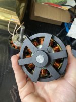
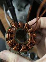
Then I moved directly to the other extreme with the 1mm wire. I think I've put 15 wires in parallel, not sure anymore. This is around 11mm2 which is pretty much what was originally installed in the motor by QS.
I had a hard time, it is not pretty but I did manage to make two full coils. I can definitely confirm it is a lot easier when you are able to fit the wires through the opening on top of each pole.

But I can also pretty much also confirm that there is no way I can double the copper fill. The slot is already full and I don't see how I could cram more wires in there. At least certainly not twice this amount!


IMG_20230224_000152.jpg

All my assumptions regarding copper fill came from using the wire and stator calculator tool:

Wire & Stator Calculator.jpg

But while this is a great tool in theory, well in practice I don't think I can trust it at all, at least not for this particular application.
The main problem is that you just can't fill slots as much because the wires have to cross each other while going from one coil to the other, so that wastes a lot of slot space. Kinda hard to explain, but basically I can't rely on this tool and will have to find the maximum copper fill by trial and error.

Also, while I successfully managed to wind these two coils physically, I did scratch them a lot. About 1/3rd of the wires were shorted to the core. The insulation paper is not nearly as tough as I expected, that's another big disappointment: it is thick so it takes a lot of space, but it isn't very tough. Also the wire insulation seem to be easily scratched, it is not very tough either.

After this mediocre success, I went trying the 1.5mm wire, 9 wires in parallel, which is 16mm2. Unfortunately this wire doesn't fit through the slots so I had to feed it by the sides. It is a lot more difficult this way, but it started well:
IMG_20230224_000136.jpg

I gave a number to each wire in order to keep them aligned:

IMG_20230223_235838.jpg

But it took only two turns to lose the nice alignment:
IMG_20230224_004455.jpg

The worst part is: that's only 2 turns! Still have one to go, and then the other coils next to it.... Absolutely no way at all that this would fit into the slots.
Plus I had one wire shorted to the core, I really need to find a way not to scrath the insulation. What a PITA.
So... yeah, big disappointment.

The only positive thing in all this mess is that the tool I've built to hold the stator works very well. I can pull like a maniac and the thing doesn't move a bit.

Anyway, it is now time to be a little more humble and to get back to earth. At that point the objective is not to put more copper than QS: it is to actually manage to put as much as they did... Lame, I know, but I guess that's the difference between a good idea on paper and the actual reality of things.

I'll keep experimenting to find better ways to wind, especially dealing with the entry/exists of each coils which seem to affect the slot fill a lot, but I believe I will go with thinner wire eventually, at least something that fits the slots since it's a lot easier. Just like you suggested @Hummina Shadeeba :)

Working with large wires is too difficult for the home gamer, the wire never stays straight no matter how hard you pull on it, you have to push it with some kind of stick, but even then it's not totally flat so that creates lots of empty spaces. Also my slots aren't square, they have very rounded edges so the coils tend not to want to conform at the top and the bottom of the slots, they all want to go to the middle. That makes packing neatly even harder.
I think I could do it relatively easily if it was only a single wire, but having the wires in parallel makes the things 10 times harder.
 
Last edited:
If you haven't seen Linguoer—mechanic's videos, you may enjoy watching her rebuild and rewind motors, and possibly learn things from the process (I did).


One of the best things about the videos is there is no annoying music, just the sounds of nature in her open-air workspace when there arent' any tool sounds. :)
 
Layers of kapton tape works well protecting the wire but especially with u having no insulation at all and thick wire I think you’d need like 10-20 layers of the standard tape thickness. To each there own but this insulation is my favorite in how it sticks/stays and u can layer it as needed. It’s Work to cut so many layers but u can find a faster method stacking strips. Or maybe what u hsve is working. I’d put more up around the head. Just need to cover those four edges of each tooth of course.
If u do the lrk winding it’s a sure thing in that since you’re only winding every other tooth you just get as many turns of wite as u can on a tooth and don’t have to worry about what will fit beside.

If I were you, and commonly done, see whats the fattest gauge wire u can fit on just one tooth of the amount of turns of wire u need, first. U could do wye or delta and give u options in how many turns u need.

If u miss a turn on a tooth or a couple because things didn’t fit as well there it’s ok and need not be perfectly consistent and I’ve read that can be even better. Then again there’s a study proving everything in the world but none the less it’s ok.


But I’m rambling about winding generally and maybe doesn’t apply to u and that one tooth u have done looks good, and the insulation as well. if u do lrk winding you’ll be able to not worry about fitting a winding in the room beside and a big relief.
 
Last edited:
I tried kapton but it was even weaker than the insulation paper and also it was almost impossible to protect certain areas since the slot is rounded.:(

I will try the official Dupont Nomex paper, I've heard good things about it

So if I understand correctly, LRK winding consists in winding only half the teeth? Don't you end up with only half the power then?
 
Last edited:
Nomex paper makes a good job. i had used it years ago for hf-windings on sharp edged ferrite cores
 
@Hummina Shadeeba: i think what works best for one motor isn’t necessarily the same as for others.

@Dui ni shuo de dui: good, steep learning curve :bigthumb: The winding calculator gives unrealistic results and doesn’t take the transit wires into account and especially if you do low turn count motors these can make you loose a full turn.

For giving the wires support on the bend around the teeth i have first blunted the sharp tooth edge with a dremel, then built up a rounding with epoxy thickened with silica powder. Mix the epoxy first, then add silica to peanut butter consistency, mix again. Cover teeth ends and leave to gel to almost non-sticky, then you can gently shape it to cover the edges (surface tension will make it want to pull away from the sharp corners ) and give a nice rounded shape. Sand to perfection (nail file has work well for me) after fully cured.

One thing to check: when the laminations have been separated and assembled again the burr side might be outwards whereas the stamped side is less sharp.

LRK winding (actually ”single layer winding” in this case): If the winding looses turns with a low turn winding on all teeth and you can avoid this by going to single layer due to better routing of transits it can be a good option.
Single layer winding has a slightly higher winding coefficient (some percent higher theoretic max torque) but has the disadvantage that you need double the turns for same kv and the end windings grow to the double (which is a LOT). The larger end turns cause higher copper losses (and in some cases the end turns don’t fit in the available space).
 
Last edited:
USER=47348]@Dui ni shuo de dui[/USER]: good, steep learning curve :bigthumb: The winding calculator gives unrealistic results and doesn’t take the transit wires into account and especially if you do low turn count motors these can make you loose a full turn.

Haha yeah, I wish I had known that earlier, kinda feel a bit disappointed now
But hopefully the final infill should be a bit higher with the new lamination stack design since the slots will be a little bit longer.

For giving the wires support on the bend around the teeth i have first blunted the sharp tooth edge with a dremel, then built up a rounding with epoxy thickened with silica powder. Mix the epoxy first, then add silica to peanut butter consistency, mix again. Cover teeth ends and leave to gel to almost non-sticky, then you can gently shape it to cover the edges (surface tension will make it want to pull away from the sharp corners ) and give a nice rounded shape. Sand to perfection (nail file has work well for me) after fully cured.
Since I am designing the stator core I was wondering if this wouln't be a good idea to slitghtly round the edges.
Something like this:

Stator  Original QS stator dimensions Copy 1 - Google Chrome.jpg
That would mean a few different plates on each side. They wouldn't be rounded in reality but more like stair shaped because each plate is flat, but then I could fill the gaps between the steps with epoxy just as you suggested. This way it wouldn't make the slots any smaller.
I don't thing that the losses would be very high if I were to do this mod, but I don't know.

Otherwise I think I'll get some side plates machined in PCB material, like the original motor used to have

Meanwhile for the tests I'll just do as you suggested: rounding the edges with a dremel. Good suggestion, thank you

One thing to check: when the laminations have been separated and assembled again the burr side might be outwards whereas the stamped side is less sharp.
Yeah, also I removed the fiberglass plate on one side because it was too damaged. That surely didn't help.

LRK: If the winding looses turns with a low turn winding on all teeth and you can avoid this by going to LRK due to better routing of transits it can be a good option.
LRK has a slightly higher winding coefficient (higher theoretic max torque) but has the disadvantage that you need double the turns for same kv and the end windings grow to the double. The larger end turns cause higher copper losses (and in some cases the end turns don’t fit in the available space).

Interesting, thanks!
I probably won't go this way since I'm not 100% sure that could work well with this particular stator/rotor configuration, but this is very interesting and I'll keep that in mind for later
 
I need to correct myself and post above in regards to the sloppy use of ”LRK” which is a winding that concerns only 12 slot 14 pole motors

The correct term is ”single layer” or ”dual layer” winding and that can be chosen and simulated in the bavaria winding calculator - if you want to see if that is an option for your slot and pole count.
 
Last edited:
How much is it costing you to get the stator made?
Getting more fiberglass plates sounds easiest for insulation. Wish there was some kind of Kevlar fiber version available
 
How much is it costing you to get the stator made?
Getting more fiberglass plates sounds easiest for insulation. Wish there was some kind of Kevlar fiber version available
I don't know the price yet, I started discussing with the supplier but he asks for 2D files while I've already sent the 3Ds, no idea why he can't simply extract the 2D from the 3Ds, thus avoiding possible mistakes later, but anyway.
I'll tell you the price as soon as I'll get it ;)

This weekend I received some Dupont Nomex paper.
It is 0.07mm thick instead of 0.17mm, so I can pass slighty larger wire (+0.2mm). It seems to be very tough, though not entirely fool proof, I'll still need to protect or round a little bit the edges. But at least I'm confident I can rewire the motor with it, it's much better than the paper I was using.
 
Last edited:

amberwolf

Feb 20, 2023
If you freeze the aluminum stator support core, it will shrink, allowing easier removal of the steel laminations, especially if you can keep the aluminum frozen while you rapidly heat the laminations (with a heatgun, etc) so that they expand outward, loosening them even more.

To install the new lamination stack, preheat it and prefreeze the core, and you might not even need a press to put them together--they may create an interference fit on their own once cooled, if the new stack is correctly cut or machined to the right tolerance to do this vs the core.

This is worth trying, used to put gears on crank shafts. Freeze the cranks and heat the gear in an oven, not with a heat gun. You will have more play than expected, for a few seconds. needs to be dropped into place. Stator would be in a vice and laminations would be aligned with out touching then dropped into place. should drop all the way into place.
 
Still experimenting with rewinding and I think now I'm starting to get it.
It seems like I will drop the idea of using thick wire, it is just too difficult, time consuming and prone to wire damage. That clearly was a noob mistake. Also while in theory that means a better fill factor, in practice it is much worse because the wire never really stays aligned and doesn't want to conform to anything. I suppose this can be done with clever specialized machinery or by spending one hour on each turn to perfectly align every single wire, but well that's not realistic for me.
So, change of plans (again?!?): I will go for the same wire thickness QS installed, or maybe a tiny tad larger (0.55 or 0.6mm maybe).

I tried with 0.54mm which is pretty much what was installed in the first place, but with 65 wires in parallel instead of 54 so that's about a 20% increase. First time I tried to tighten the wires vey hard against the poles:

IMG_20230227_222854.jpg
IMG_20230227_222907.jpg
It looks quite clean, but it was difficult to do and I'm not 100% sure I have enough space to fit the coils next to it.
The positive point with this winding technique is that the endturns are as small as can be, so that's a lot less losses and a lot less useless copper.
The negative point is that the wire get scorched very easily, unfortunately the nomex paper isn't some magical thing and I got a few wires making contact with the core. I will definitely need a way to protect the wires from the core in the final version, this seems like the biggest issue remaining to me now.

Next, I tried a different approach. I had an other look at the pictures I took of the motor before dismantling it, and noticed that the coils were not tightly packed against the cores. Instead, they were pretty loosely wound, it seems like they voluntarily let them loose for easier winding, then apply some kind of glue so the wires don't wander around because of the vibrations.
So I tried to replicate this:


IMG_20230227_233122.jpg

IMG_20230227_233130.jpg

It's a tiny bit too loose on this side, that was my first attempt so I shall get better with more practice, but it's not too bad

Well, that was a lot easier. Took me way less time, way less drama and it seems like I've got even a little bit of room to fit maybe 5 more wires. Interesting.
So basically, I think I will have to choose between shorter end turns but potentially less fill between stator poles, or longer end turns but more wires in parallel.

If I'm being honest, I prefer the neat looks of the first one, but it was sooo much easier to wind with the second method... Also thess chances to scratch the wire when you're not pulling on it like a maniac. Anyway, the great news is that I seem to be able to fit 20% more copper this way with the original slot size, so the final improvement with the longer slots should be quite substantial.

I'm just not sure what's best performance wise: shorter end turns or more paralleled wires ?
 
Very interesting, if only,:(
All good, but the motor winding stuff starts bout 20 min into video
 
Last edited:
Your Nomex paper looks really thin. The stuff I used was like card stock. No issues with the insulation. I "glued" them in place with some varnish before winding. The paper extends beyond the slot enough to cover the sharp edge. (sorry for the bad picture)

DSCF0059.JPG
 
Your Nomex paper looks really thin. The stuff I used was like card stock. No issues with the insulation. I "glued" them in place with some varnish before winding. The paper extends beyond the slot enough to cover the sharp edge. (sorry for the bad picture)
Haha this picture gave me eye cancer, but worth it! Thanks!
Yeah you are right, I will get thicker stuff eventually, I really don't want to wind the whole thing only to discover that a wire is shortened to the core, would suck.
Great idea to glue them before winding, I'll keep that in mind, thank you!

Meanwhile I'm still training my winding skills everyday, finally starting to get better:

IMG_20230301_181518.jpg
That's 65 wires in parallel, this time I did a transition between 2 ends of 3 sets of coils, which is where there are the most turns (3 turns on each side, each one having 65 wires so the most filled slot has actually 390 wires going through!!). I think I'm close to the limit, I can probably fit one or two more wires but not much more.
But with he final slots being longer, I suppose I could reach 70 paralleled wires, mayyyybe 75? Will also depends if I'm using thicker insulating paper or not. That would be a nice increase over the 54 wires it originally had.

But at least now the coils start to look a bit cleaner, I think I'm starting to get it.
 
Back
Top