Doctorbass
100 GW
The Meanwell RSP power supply serie is one of the highest quality and compact charger solution for high power and the RSP serie is great but there is one missing feature we woudl like to have on it: CURRENT LIMIT ADJUST !!!
I am using like 7 of these power supply. Recently i built a 6.6kW charger using these for my Zero motorcycle.
At full power ( CC CVmax) It require 30A at 240V. This is perfect for the most common level 2 charging station of 30A.
However problem is that if i'm charging on a charge station that is on 208V and not 240V it will draw 35A+ and will trip the 30A protection circuit of the charge station.
To solve that i need to be able to adjust the actual current limit to a lower value when desired.. ex: when having 208V input instead of 240V...
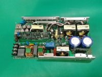
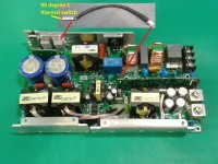
I got from my work a deffective RSP-750 (http://www.meanwell.com/search/RSP-750/RSP-750-spec.pdf) witch is perfect for deep investigation on how is the current limit designed and ito know if could install a current adjust feature with the RSP.
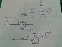
I have decided to reverse engineer a part of the circuit but i will some need help on that. What i'm looking for is the proper resistor that i can modify or add a pot to change the actual current limit.
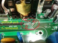
Here is couples pictures of it and of the curent sense section with the shunt resistor on the back of the pcb.
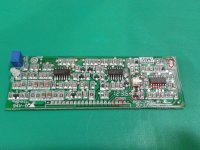
You can see that close to the 3 parallels shunts resistors there is some holes i pointed with teh arrow. I'm sure These holes are for the current sensing to conduct the measured voltage across the parallel resistor to a trace that goes to the vertical daughter smd PCB.
I am using like 7 of these power supply. Recently i built a 6.6kW charger using these for my Zero motorcycle.
At full power ( CC CVmax) It require 30A at 240V. This is perfect for the most common level 2 charging station of 30A.
However problem is that if i'm charging on a charge station that is on 208V and not 240V it will draw 35A+ and will trip the 30A protection circuit of the charge station.
To solve that i need to be able to adjust the actual current limit to a lower value when desired.. ex: when having 208V input instead of 240V...
I got from my work a deffective RSP-750 (http://www.meanwell.com/search/RSP-750/RSP-750-spec.pdf) witch is perfect for deep investigation on how is the current limit designed and ito know if could install a current adjust feature with the RSP.
I have decided to reverse engineer a part of the circuit but i will some need help on that. What i'm looking for is the proper resistor that i can modify or add a pot to change the actual current limit.
Here is couples pictures of it and of the curent sense section with the shunt resistor on the back of the pcb.
You can see that close to the 3 parallels shunts resistors there is some holes i pointed with teh arrow. I'm sure These holes are for the current sensing to conduct the measured voltage across the parallel resistor to a trace that goes to the vertical daughter smd PCB.