Shenzhen (ecrazyman) Controller Information

Stevil_Knevil said:
Success!!
Here is the color-coding to connect the Shenzhen controller to a 400 series C-lyte motor:
Hall sensors-
Blk :arrow: Blk
Red :arrow: Red
Yel :arrow: Yel
Grn :arrow: Blu
Blu :arrow: Grn

Phase-
Blu :arrow: Yel
Grn :arrow: Grn
Yel :arrow: Blu

Wow Stevil, you just saved me a lot of re-work on my x5 install with this - THANK YOU!

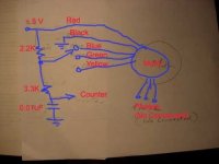
I used Fechter's directions (THANK YOU TOO!) to install a CycleAnalyst connector (minus speedo/hall). I have to think these through each time I do them, so I though some pics might help if anyone else is as dumb as me. The colors on my connector are different, so I include a pic to show you that. I really appreciated the grommet setup on the Shenzhen - each wire has its own individual hole, somewhat sealed, and there were 6 free holes

-JD
View attachment 4
View attachment 3
1-black_IMG_1261.JPG
2-gray_3-brown_4-green_IMG_1268.JPG
6-red_IMG_1258.JPG
 
Knuckles & Keywin, Much respect to you for bringing this controller to myself and other Spherites! You guys RAWK!!

ngocthach1130, Check the ebikes.ca Hub Simulator. A 404 @ 72V in a 16" wheel w/ ~35A thrown at it will spin up to ~55 MPH :shock: :twisted:

Oatnet, Thanks for fleshing-out Fechter's illustration of the Shenzhen/CycleAnalyst connectivity.. that was next on my 'to do' list :wink:
 
Knuckles said:
Keywin tested the Bafang no-load at 88V (no wheel ... just the hub motor mounted for testing).
He said it sounded like a jet engine because it was spinning at over 450 rpm.

Heck ... I bet my Grubee motor is more evil than Stevil_Knevil. Check my vid here ...
[youtube]m7-MGsZ27XU[/youtube]

cheers
What is the motor in this vid?
 
Knuckles said:
Tiberius said:
Hi Knuckles,

(I mean Mr Knuckles, sorry) What is the model number of the Bafang motor you are testing - and is it front or rear wheel?

I have a motor and controller on the way from Keywin, so I may be able to run some similar tests soon.

Nick
Awh Heck ... Call me Knuckles! :oops:

Cool. Keywin mentioned he just sold a motor. I guess that was you.
My test motor is a front wheel but they are eactly the same motor (front and back).
I don't know the model #. I believe it is 36V-250W. Maybe. Keywin no-load tested it at 88V.

I can't wait to here your results. 72V and 30-amps?

Please do tell!

OK Knuckles, it sounds like I'm getting the rear version of the same motor. Nominally 36 V 250 W, but those are only the "nominal" figures, right? Its somewhere in transit at the moment. The plan is to do a comparison with the C-Lyte 406. I'm expecting the C-Lyte will be better on top speed but that the Bafang will be better at lower speed hill climbing.

Nick
 
Don't let the Watt rating fool you. To me it's the mass of copper that is important. And the Bafang comes in different flavors. Don Grubee loves them.
Since this is a geared motor and the rotor spins 4 to 5 times faster than a Direct Drive. The mass of copper will be half as much for same power.

I suspect that the Bafangs all have the same mass of copper but are wound differently to produce these PMGR models ...

24V - 200W
36V - 250W
48V - 350W

I also suspect that they will all run fine at 72V and 30 amps. The 24V will run fastest (and hotter). The 48V will run slowest (and cooler).
Just different motor constants (K rpm/v). That's my guess. Gotta love testing!

Please note: I edited this post as information becomes more accurate. I am hunting down specs too.
 
Stevil_Knevil said:
Success!!

http://www.youtube.com/watch?v=g48zLEEPIQc

Here is the color-coding to connect the Shenzhen controller to a 400 series C-lyte motor:

Knuckle-troller :arrow: C-lyte

Hall sensors-

Blk :arrow: Blk
Red :arrow: Red
Yel :arrow: Yel
Grn :arrow: Blu
Blu :arrow: Grn

Phase-

Blu :arrow: Yel
Grn :arrow: Grn
Yel :arrow: Blu

Note: connecting color :arrow: color will drive the motor backwards quite nicely.

Edited for improved content & clarity

This color matching is to "drive the motor backwards".
Did you note the battery current?

Have you try for the forward direction?
If so, could you state the color matching also.
 
I had a discussion on phase/hall wiring with a forum member. He said there are 36 possible combinations.
I disagreed. I say there are only six possible combinations. I was close but not exact.

THERE ARE ONLY 6 POSSIBLE combinations (and only one will work) BUT only for a single direction.

When you find the right combination (1 out of 6) AND the direction is FORWARD then you are lucky.
If the direction is BACKWARD then switch 2 of the Hall wires and try the six (3-phase wire) combinations again.

This time when you find the right combination (1 out of 6) the direction WILL BE FORWARD.
See my xls spreadsheet here ... http://98.131.176.65/endless-sphere/Phase-Hall-Wire-Combinations.xls

cheers
 
Knuckles said:
I had a discussion on phase/hall wiring with a forum member. He said there are 36 possible combinations.
I disagreed. I say there are only six possible combinations. I was close but not exact.


I concur with you that you don't need to test all the 36 possible combinations.
It is only needed to test 12 combinations according to the first two columns according to your xls.
The remaining 24 combinations would have the identical results as these 12 combinations.


Assume a,b,c and A,B,C are Hall and Phase of the controller; and
x,y,z and X,Y,Z are Hall and Phase of the motor.

If the phase-sequence is A-B-C and the correct match is
Combination (1)
a - x
b - y
c - z
A - X
B - Y
C - Z

Then the two identical matches are
Combination (2)
a - y
b - z
c - x
A - Y
B - Z
C - X

and Combination (3)
a - z
b - x
c - y
A - Z
B - X
C - Y
 
You are one sick dude! Did you figure this out by testing or in your mind?

The7 said:
Knuckles said:
I had a discussion on phase/hall wiring with a forum member. He said there are 36 possible combinations.
I disagreed. I say there are only six possible combinations. I was close but not exact.


I concur with you that you don't need to test all the 36 possible combinations.
It is only needed to test 12 combinations according to the first two columns according to your xls.
The remaining 24 combinations would have the identical results as these 12 combinations.


Assume a,b,c and A,B,C are Hall and Phase of the controller; and
x,y,z and X,Y,Z are Hall and Phase of the motor.

If the phase-sequence is A-B-C and the correct match is
Combination (1)
a - x
b - y
c - z
A - X
B - Y
C - Z

Then the two identical matches are
Combination (2)
a - y
b - z
c - x
A - Y
B - Z
C - X

and Combination (3)
a - z
b - x
c - y
A - Z
B - X
C - Y
 
Knuckles said:
You are one sick dude! Did you figure this out by testing or in your mind?

The7 said:
Knuckles said:
I had a discussion on phase/hall wiring with a forum member. He said there are 36 possible combinations.
I disagreed. I say there are only six possible combinations. I was close but not exact.

I concur with you that you don't need to test all the 36 possible combinations.
It is only needed to test 12 combinations according to the first two columns according to your xls.
The remaining 24 combinations would have the identical results as these 12 combinations.

Knowledge is not necessarily always derived from testing.
Discernment should be based on engineering principle and experience.
 
The7 said:
Stevil_Knevil said:
Success!!

Here is the color-coding to connect the Shenzhen controller to a 400 series C-lyte motor:

Knuckle-troller :arrow: C-lyte

Hall sensors-

Blk :arrow: Blk
Red :arrow: Red
Yel :arrow: Yel
Grn :arrow: Blu
Blu :arrow: Grn

Phase-

Blu :arrow: Yel
Grn :arrow: Grn
Yel :arrow: Blu

Note: connecting color :arrow: color will drive the motor backwards quite nicely.

Edited for improved content & clarity

This color matching is to "drive the motor backwards".
Did you note the battery current?

Have you try for the forward direction?
If so, could you state the color matching also.

There is no reverse jumper (at least not that I have found).

When I first tested this controller, I noticed that if I match the colors on all the hall and phase wires, the motor ran reversed. The color matching shown above will make it run forward.
This assumes a Crystalyte or similar motor.
 
Hi Guys,

Right, I just received my controller and motor today from Keywin (ecrazyman). One week from ordering it from the other side of the globe, which can't be bad. There are 3 wires on it that I didn't understand, but fechter's diagrams on page 1 of this thread explain them.

The model number I have is BL7828 instead of the BL7228 that fechter reports.

I spent this evening building a test frame to mount the motor in. I'll try to run it up and report as soon as I can. I've got a set of 30V lab power supplies I can connect in series.

Nick
 
The7 said:
Knowledge is not necessarily always derived from testing.
Discernment should be based on engineering principle and experience.
So are you saying (as an experienced engineer) that ... "One opinion is worth a thousand tests"?

Cosmic! In this instance you are correct as the solution is math.

Imagine a Direct Drive Motor (no gears - no PMGR).

Imagine the three phase motor wires as nodes A, B, C in an equilateral triangle. Each node is “associated” with a motor hall sensor a, b, c.
Imagine the “firing” order of the controller phase wires (PWM controlled by throttle) as I, II, III timed to the hall sensor (signal) order 1, 2, 3.

Now this is a triangle. You can go around the triangle (start at A) clockwise (forward) to B and then to C. But you can also go counterclockwise A to C to B (reverse).
Assume a,b,c and A,B,C are Hall and Phase of the motor; and 1, 2, 3 and I, II, III are Hall Signal and Phase firing order of the controller.

If the phase-sequence is A-B-C and the correct match (forward direction) is Combination (1)
(motor-controller)
a - 1
b - 2
c - 3
A - I
B - II
C - III

Then the two identical matches are Combination (2)
a - 2
b - 3
c - 1
A - II
B - III
C - I

and Combination (3)
a - 3
b - 1
c - 2
A - III
B - I
C - II

And of course the correct phase-sequence for reverse direction (Combination 1) is
a - 1
c - 2
b - 3
A - I
C - II
B - III
 
Knuckles said:
Imagine the three phase wires as nodes A, B, C in an equilateral triangle. Each node is “associated” with a hall sensor a, b, c.
Imagine the “firing” order of the phase wires as I, II, III timed to the hall sensor (signal) order 1, 2, 3.

Now this is a triangle. You can go around the triangle (start at A) clockwise (forward) to B and then to C. But you can also go counterclockwise A to C to B (reverse).
Assume a,b,c and A,B,C are Hall and Phase of the controller; and 1, 2, 3 and I, II, III are Hall Signal and Phase firing order of the motor.

If the phase-sequence is A-B-C and the correct match (forward direction) is Combination (1)
a - 1
b - 2
c - 3
A - I
B - II
C - III

Then the two identical matches are Combination (2)
a - 2
b - 3
c - 1
A - II
B - III
C - I

and Combination (3)
a - 3
b - 1
c - 2
A - III
B - I
C - II

And of course the correct phase-sequence for reverse direction (Combination 1) is
a - 1
c - 2
b - 3
A - I
C - II
B - III

The reverse direction (Combination 1) is correct ONLY IF the phase relationship between the Hall signals and the phase BEMFs of the motor in the reverse direction are the same as that in the forward direction.

But this combination is not correct since the BEMF in reverse rotation is negative of that in the forward rotation and this will give an addition of 180 deg.

You could check the result of the MYSTERY MOTOR in your xls.

For Controller:
Let a = Hall Blue
b = Hall Green
c = Hall Yellow
A = Phase Blue
B = Phase Green
C = Phase Yellow

For Motor
1 = Hall Blue
2 = Hall Yellow
3 = Hall Green
I = Phase Blue
II = Phase Yellow
III = Phase Green

This equivalent ones are marked in the modified xls from yours.

Then the forward combination is
a - 1
b - 2
c - 3
A - I
B - II
C - III

And the reverse direction combination becomes
a - 1
c - 2
b - 3
A - II
C - III
B - I
 

Attachments

  • Phase-Hall-Wire-Combinations aa.xls
    21 KB · Views: 123
Hi guys,

Here's a quick preliminary report. I got my ecrazyman controller and Bafang motor yesterday. Last night I made a little test stand for the motor and today I ran it all up. I solved the sensor/winding wire puzzle by trial and error (OK, I did use advanced mathematical techniques to make sure it took only the minimum number of trials). Then I could take it to 330 Hz on the Hall sensors.


There are scope traces, but for now there's no point publishing them - I need to resolve a few issues first.
I am using 3 PSU's in series to make a source that can be adjusted up to 90 V. Look carefully and you can see the diodes strapped across each one. The blue PSU is the throttle.
There's a lot of noise on the signals, so scope triggering is an issue. Noise is much worse at partial throttle.
The current limits on the PSUs keep triggering - this alone could invalidate any results.
For some reason, the system won't let me get above 71.9 V. If I try to push it, the noise changes slightly. I need to work out if that is PSU, controller or the combination interacting. I suspect its the combination.
Keywin has modded the controller low voltage cut off so I can switch between 36 and 72V operation. I need to get my head round that first.

But so far, it does what would be expected and I haven't seen any strange behaviour other than the 71.9 limit.

Nick

PS. Edited to add: I deliberately downsized the picture to make it display comfortably, only to find the system does that for you.
 
BTW, its a geared motor with freewheel.

Don't know if this is sad or what, but I just put a counter on one of the Hall sensors and turned it backwards one turn. Keep getting a count of 86. For some reason I was expecting it to be a multiple of 3, but I don't suppose it has to be anything special if its geared.

Nick
 
Excellent test setup!

btw. I just use two 36V SLA chargers is series as an 88V PSU for no-load testing. That works perfect for my controllers and DD brushless motors.

See my vid here ...
[youtube]WkPE3DaqbV8[/youtube]
 
Thanks Knuckles,

It isn't only used for this, though. But something needs checking. I just crunched the numbers on the rates and rpms and it works out as about half the road speed it should be doing.

fechter, doc, anyone, what kind of Hz per Volt do you expect from the typical geared motor? I mean Hall sensor Hz / Supply V at no load.

Nick
 
Knuckles said:
btw. I just use two 36V SLA chargers is series as an 88V PSU for no-load testing. That works perfect for my controllers and DD brushless motors.

I don't have any of those, unfortunately. I do have various 5 A PSUs but they only add up to about 50 V.

What I do have is breadboard dc-dc step up converter that will make hi V from a car battery. I've only run it up to 80 V so far, but there's more there. But its not finished and I don't want to put too many uncertainties into the test.

Nick
 
Nice setup!

I'm not sure there is a "typical" bike motor of any type these days. You could open the side cover and count the magnets.

The behavior you're describing sounds like what I was getting at around 31v with the Puma. Above that voltage, the rpm got to that critical frequency and started to spike the current.

If you put the scope on any hall signal and the hall ground, it should look pretty clean. From this you could determine the frequency. The signal on the phase wires is normally very noisy.

You could also put the scope across the power input to the controller to see if the PSU current limiter is kicking in.
 
Tiberius,

You have an excellent setup to test any motor at no-load with an supply voltage up to 90V.

I hope that you don't mind if I make some suggestions and comments about the test.

1) "The current limits on the PSUs keep triggering - this alone could invalidate any results"
What are the current limits used?
Would suggest to be about 2 or 3 A for no-load test.
There is one main difference between battery and PSU. Battery could supply current (forward current) and take back current (reverse current). PSU could only supply current but NOT take back. There could be some "reverse current" from the motor. These PSUs could be too sensitive to the reverse current.

2) Use the lowest supply voltage to determine the best combination for the forward. The best combination will give the minimum supply current. The supply current could be read in the PSU. In your case the lowest voltage is 36V for this controller.

3) "I solved the sensor/winding wire puzzle by trial and error (OK, I did use advanced mathematical techniques to make sure it took only the minimum number of trials)."
Noted that you have already achieved this by trial and error.

4) "I am using 3 PSU's in series to make a source that can be adjusted up to 90 V. Look carefully and you can see the diodes strapped across each one. "
How did you connect these diodes?
Are these diodes are connected in reverse and across each PSU?

5) "There's a lot of noise on the signals, so scope triggering is an issue. Noise is much worse at partial throttle."
Try to use one channel to measure for one certian Hall signal and only use this channel for triggering.
Then use the other channel to measure each of the other Hall signals, motor phase voltages ( one at a time) wrt the -ve of the supply (as close to the controller as possible).
Measure also the time period for 1 cycle of the Hall signal and its frequency could be calculated from its time period. The frequency of motor phase voltage is same as the Hall signal.

6)"BTW, its a geared motor with freewheel. Don't know if this is sad or what, but I just put a counter on one of the Hall sensors and turned it backwards one turn. Keep getting a count of 86. For some reason I was expecting it to be a multiple of 3, but I don't suppose it has to be anything special if its geared."
How did you measure?

A simple circuit as suggested in the attached picture could be used to measure the Hall signal from one sensor with counter.
It uses one 5 V supply , pull-up resistor of 2.2k and simple noise filter of 3.3k and 0.01uF for the countor.
No of counts for 1 turn = No of pole-pairs X Gear-ratio
If this motor has 10 pole-pairs and gear-ratio of 4.3 (this data 4.3 was mentioned by Knuckles?)
Then no of counts for 1 turn = 10 x 4.3 = 43 counts.

If your counter counts the edge of rising and the edge of falling as 2 counts, then the number will be double .

7)"For some reason, the system won't let me get above 71.9 V. If I try to push it, the noise changes slightly."
Did you note the frequency at this instant?
It could be the same critical frequency as observed by fechter.

8) "What I do have is breadboard dc-dc step up converter that will make hi V from a car battery. I've only run it up to 80 V so far, but there's more there. "
What is frequency at 80V?
Would like to see the voltage waveforms on scope for full throttle and partial throttle.
Especially at partial throttle to see if the phase voltage is symmetrical or not.
 

Attachments

  • Counter DCN8113 copy.jpg
    Counter DCN8113 copy.jpg
    15.7 KB · Views: 3,706
Hi The7,

All very interesting points, thanks. I think I'm going to go back and check everything again before I respond in detail.
Your comment about 10 pole and 4.3 ratio is a bit spooky if I'm counting 86. There are too many parameters out by factors of two here for comfort. I need to check stuff, let you know more tomorrow.

Nick
 
The7 said:
The reverse direction (Combination 1) is correct ONLY IF the phase relationship between the Hall signals and the phase BEMFs of the motor in the reverse direction are the same as that in the forward direction.

But this combination is not correct since the BEMF in reverse rotation is negative of that in the forward rotation and this will give an addition of 180 deg.

Gosh! OK so I forgot about the old 180 degree BEMF forward-reverse gig! details details details!
So here is a design for a DPDT forward-reverse relay setup.

F-R_dpdt_relays.jpg
btw My Bafang is on it's way to me now so I'll post my testing here also.

Tiberius, Can you open up the controller? I am curious what components Keywin sent to you. 80nf10 fets? LVC=62V? Pics of mods on the pcb?
Toa Chie.
 
Back
Top