Shenzhen (ecrazyman) Controller Information

docnjoj said:
On a 20" wheel it should still run about 20 mph (Pi* 20=63 inches*240=15120"/12=1260'/60=21mph or 29.5kph. Not bad for an old guy on a trike, but not suitable for young speed demons! Of course my math could be wrong! I did see the 23 kph above.
other Doc

Note: 1260'/60=21 ft/sec (Not mph)
21 ft/sec = 1260 ft/min = 1260 x 60 /5280 mph = 14 mph. (=> 23 km/h)
 
The7 said:
So far as observed:

1) Shenzhen (ecrazyman) Controller has a cut-off (or critical) frequency of about 325Hz. I think this cut-off frequency is programmed in the MCU.

2) It will behave normally if the output frequency is lower than the cut-off frequency.

3) The cut-off rpm of rotor = The cut-off frequency X 60 / (No of pole-pairs)
If the no of pole-pairs = 16 (say for the Puma) .
Then the cut-off rpm of the rotor = 325X60/16 = 1218 rpm

4) If the motor does not reach the cut-off rpm at a certian battery voltage at full throttle, you will not notice it at all.

5) If you use a higher battery voltage, the motor will reach the cut-off rpm at a partial throttle. The position of the partial throttle depends on the battery voltage
Some comments:
A) It is a good feature to have an cut-off frequency ( cut-off rpm) so that the legal maximum assisted only speed does not exceed the legal speed limit.
But it should be selectable by the end-users because the end users could have motors of various pole-pairs and gear ratios.

B) At rpm near the cut-off rpm, the controller should not behave abnormally to cause any damage to the motor and/or to the controller itself. The controller should reduce the power gradually when the motor approaches the cut-off rpm and cut-off the power when it exceeds.

C) It seems that this controller does NOT fully satisfy (A) and (B).

Hi The7,

That sums it up, but the fact that it doesn't satisfy (B) makes me think its not a deliberate feature. It looks like a timing problem, either in the MCU or in the response time of part of the circuit. On the other hand, 325 Hz is pretty low to be running into that.

IUIIC, these tests are done at 100% throttle, with the voltage varying. So the BEMF is always close to the available voltage. It would be useful to see what's going on with the hi side FETs.

HTH,

Nick
 
Hi Nick,

Cut-off frequency of 325Hz could be too low for geared hub motors like Puma.
But it will not cause any problem for geareless hub motors like Crystalyte 5xxx/4xxx because the cut-off speed is well over 100 km/h.

I have done some test on old version Crystalyte and Ananda controllers.
Ananda has PWM on the low side FETs.
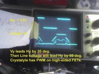
Crystalyte has PWM on the high side FETs.

I think that this controller has PWM on the high side FETs.
I would like to see the gate signal on the high side FET near the cut-off frequency as well.
 
The7 said:
docnjoj said:
On a 20" wheel it should still run about 20 mph (Pi* 20=63 inches*240=15120"/12=1260'/60=21mph or 29.5kph. Not bad for an old guy on a trike, but not suitable for young speed demons! Of course my math could be wrong! I did see the 23 kph above.
other Doc

Note: 1260'/60=21 ft/sec (Not mph)
21 ft/sec = 1260 ft/min = 1260 x 60 /5280 mph = 14 mph. (=> 23 km/h)
Darn! Thats why they said to go to doctor school from engineering! Less math!
Thanks
other Doc
 
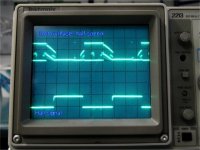
Comparing the motor phase voltage waveforms of my old version Crystalyte controller and this S controller (picture from Fechter) at about half speed (partial throttle):

1) Both have PWM on the high side FETs.
2) The waveform of C is symmetrical.
3) The waveform of S is not symmetrical. There is an high spike at the start of increasing.
 

Attachments

  • Crystalyte Controller.jpg
    Crystalyte Controller.jpg
    33.2 KB · Views: 4,509
  • Puma half speed_a.JPG
    Puma half speed_a.JPG
    45.4 KB · Views: 4,695
docnjoj said:
The7 said:
docnjoj said:
On a 20" wheel it should still run about 20 mph (Pi* 20=63 inches*240=15120"/12=1260'/60=21mph or 29.5kph. Not bad for an old guy on a trike, but not suitable for young speed demons! Of course my math could be wrong! I did see the 23 kph above.
other Doc

Note: 1260'/60=21 ft/sec (Not mph)
21 ft/sec = 1260 ft/min = 1260 x 60 /5280 mph = 14 mph. (=> 23 km/h)
Darn! Thats why they said to go to doctor school from engineering! Less math!
Thanks
other Doc

We are both retired. Take care units not maths!
 
Exactly.

Even in medical-math: Xmg dosage / Patient-kg... don't pull a NASA. (metric/english errors = trouble)

:mrgreen:
 
Funny! My last 15 years I taught Pharmacology (neutered by administration, love that phrase). Didnt make too many errors, cause ifn' U do, U see dead people! Need a brain reboot!
other Doc
 
Hey Fechter,

Wonder if you could post a wire color/schematic or pic of the phase and hall connections from this controller to the BMC? I have one of these Knuckle-trollers, a C-lyte 404 16" and 72V-10Ah SLA pack that I would like to introduce to each other.. but ZERO spare throttles in the (likely) event that I get the wires mis-matched :oops:

Many thanks, -S
 
Take a look at this post for wiring setups ... http://endless-sphere.com/forums/viewtopic.php?f=2&t=4370
 
I won't pretend to understand everything...
but AWESOME thread. Love the LVC hack. I may just buy a controller now!
 
Stevil_Knevil said:
Hey Fechter,

Wonder if you could post a wire color/schematic or pic of the phase and hall connections from this controller to the BMC? I have one of these Knuckle-trollers, a C-lyte 404 16" and 72V-10Ah SLA pack that I would like to introduce to each other.. but ZERO spare throttles in the (likely) event that I get the wires mis-matched :oops:

Many thanks, -S

All of my BMC motors have "alien" color codes, so what I have won't necessarily match what anyone else has:

Puma wires------Shenzhen wires
Hall sensors------colors match

Phase Blue------Yellow
Phase Green------Blue
Phase Yellow------Green


The hall and phase wires should match the colors on a Crystalyte motor.

The Shenzhen throttle connector is:
Black = ground
Red = +5v
green = signal (wiper)
 
In fact there are only six combinations. Heck try them all ... it won't cause damage.

Here is an email I sent to my new buddy in Costa Rica ...

"I have two Grubee (non-geared) BL motor flavors ... 36V (350W rating) and 48V (500W rating). I run both of these at 80V and 30 amps so more like 1200W delivered to the road easy.
The 36V motor is faster (more rpm) and the 48V motor is higher torque (better in sand and mud).
I take motors apart a lot because at high loading (acceleration or hill climbing) I think heat in the motor is burning out the Hall Sensors.
See my post here http://endless-sphere.com/forums/viewtopic.php?f=2&t=4464
I may switch to a pedal first controller if Keywin can make them too.
I do like the immediate start controller though.

Shipping motors is a bitch because of the weight. I'll work up a price for you on a motor w/ shp costs. You decide between high speed or high torque.

On the Hall Sensor wires. Use your best guess to decide which is the positive (red) and which is the negative (black). Hook these up to the controller hall sensor plug. Then pick any other color combo for the remaining three Hall signal wires (yellow, green, and blue). No need to connect the phase wires or throttle just yet. Provide a 72V power supply to the controller (black is negative and orange/red are positive). It will spark when you connect it. This is normal (caps are charging).

Put a volt meter black to the (assumed) hall neg then use volt meter red to measure the three Hall signal wires. slowly turn the motor (or axel) and each hall signal wire should vary between 0 and 5 V as you slowly turn the motor.
If they vary then you guessed right on the + and - Hall leads. If not then try again.

Hook up throttle.

Hook up phase wires (six possible combinations).

Try each phase wire combination until motor runs smoothly (and in a forward direction).

bada bing. Your ready to ride!"

K
 
Knuckles said:
On the Hall Sensor wires. Use your best guess to decide which is the positive (red) and which is the negative (black). Hook these up to the controller hall sensor plug. Then pick any other color combo for the remaining three Hall signal wires (yellow, green, and blue). No need to connect the phase wires or throttle just yet. Provide a 72V power supply to the controller (black is negative and orange/red are positive). It will spark when you connect it. This is normal (caps are charging).

Put a volt meter black to the (assumed) hall neg then use volt meter red to measure the three Hall signal wires. slowly turn the motor (or axel) and each hall signal wire should vary between 0 and 5 V as you slowly turn the motor.
If they vary then you guessed right on the + and - Hall leads. If not then try again.

Hook up throttle.

Hook up phase wires (six possible combinations).

Try each phase wire combination until motor runs smoothly (and in a forward direction).

bada bing. Your ready to ride!

K

Pretty damn-good instructions - for a Knuckle-head :wink:

I dusted-off Maytag's BMC/C-lyte wiring diagram.. just for cross-referencing:

file.php


http://endless-sphere.com/forums/viewtopic.php?t=541&start=8

Hey, about the Grubee geared motors; have you bugged Mr. G for a test sample(s)? :twisted: :twisted: :twisted:
 
Ah-Hem! That is "Knuckle-head ENGINEER" thank you very much! Actually it is "MR. Knuckle-head ENGINEER". I just needed to set that straight! 8)

Looks like you are now our resident Maytag repairman! Don't worry, however, you will be BUSY!

I generally try to "bug" Grubee every month or so. He's a funny dude (arrogant as hell - LIKE ME :D ). Don is Mechanical Engineer. Been in the motor business for decades. He lives in Oklahoma (I think) but his wife is Chinese. He travels to China a lot. He's been importing electric starters from China for like EVER. Lives there too I think. Don got his first gas-bike kit many moons ago and has been hooked on powering bicycles ever since. His motors have good rep in Asia. I think he selling most there right now.

He don't seem to care about ebay or forums or such right now. I bug him but he don't care and only sell by container load. That's OK. I'll find a way!
 
fechter said:
I took my standard test motor and gave it enough voltage to hit 325 Hz and the jitter still happened. My test motor is very small, neutrally timed, wye configured. At full speed it draws about 0.25 amps no load. When the jitter starts, the current jumps to over 1 amp.

BTW, the Shenzhen controller has what appear to be connection points for a PIC in-system programmer interface. The MCU appears to be something like a PIC16F72.

Fechter discovered there is an "critical" frequency of about 325 Hz for this Shenzhen controller which uses some standard "digital MCU" board. He has done extensive tests and reported his down-to-earth findings.

Shenzhen controller behaves well for power frequency less than the critical frequency. But it will behave very abnormally if it is only very slighlty above this critical frequency. The current could increase abnormally and damage the motor and the controller it

We have tried to find out "WHY? ".

Up to now some possible causes and comments are:

1) The analog delay in the LP filter at the Hall signal input. But the abnormal increase in current for a slight increase in frequency is very sudden. So it does not seem to be the cause beacuse the change in analog circuit is no so sudden.

2) The digital delay in processing in the MCU. Don't think this is the cause because the MCU speed is very, very high.

3) There is a pre-program for overspeed in the MCU. Don't think this simple MCU has such program. Even if it has, it should not cause the sudden abnormally increase of the current, but should reduce the current gradually when overspeed.

I try very to recall my knowlege of digital signal processing, filtering and signal representation to see if there is another possible cause.

One other possible cause could be due to the limitation of the digital representation of an analog signal when the analog signal exceeds the limit value.

Let me illustrate by using an 2-bit word to represent 4 levels of analog signal (say 0 to 3 Hz).
00 = 0
01 = 1
10 = 2
11 = 3
The limit frequency is 3 Hz

What will be the digital representation if the frequency is 4 Hz (1 Hz about the limit 3Hz)?
In 2-bit math:
11 + 01 = 00
Now it becomes 0 Hz for the MCU, the MCU will give a "wrong" output and cause the abnormal change.

Assume that this controller uses an 16 bit word to represent 65536 levels of frequency (0 to 65535).
Level 0 => 0 Hz
Level 65535 is used to represent the limit frequency (say, the critical frequency at 325 Hz).
Each level = 325 /65536 = 0.005 Hz.
The digital representation will be completely "wrong" if the frequency is slightly above the limit frequrncy.

Apparently the board of this controller was designed on the understanding that the power frequency will never exceed the critical frequency (about 325 Hz) which is valid for gearless hub motors.
 
Another possibility is a bug in the code that causes a loop back or program branch at the wrong point when the critical frequency is exceeded. This bug could be dependent on some other parameter other than speed, causing the problem to happen only under certain conditions (which I seem to have created). This could possibly be fixed by changing something in the code.

In the case of the Crystalyte v.2 controller, there are some reports of it working and other reports of it not working, despite apparently the same program.
 
And yet Keywin just tested a Bafang PMGR at 72V (400 rpm wheel speed - maybe 3000 rpm rotor speed) and no jitter was reported.
See ... http://endless-sphere.com/forums/viewtopic.php?f=2&t=4482
Motor ran smooth or as Keywin said "sounds like jet engine". Amp draw stayed constant at 0.8 amps.
So something is 'a foot' with the PUMA and BMC controller interaction.

The mystery remains ...
 
Hi Knuckles,

(I mean Mr Knuckles, sorry) What is the model number of the Bafang motor you are testing - and is it front or rear wheel?

I have a motor and controller on the way from Keywin, so I may be able to run some similar tests soon.

Nick
 
Tiberius said:
Hi Knuckles,

(I mean Mr Knuckles, sorry) What is the model number of the Bafang motor you are testing - and is it front or rear wheel?

I have a motor and controller on the way from Keywin, so I may be able to run some similar tests soon.

Nick
Awh Heck ... Call me Knuckles! :oops:

Cool. Keywin mentioned he just sold a motor. I guess that was you.
My test motor is a front wheel but they are eactly the same motor (front and back).
I don't know the model #. I believe it is 36V-250W. Maybe. Keywin no-load tested it at 88V.

I can't wait to here your results. 72V and 30-amps?

Please do tell!
 
Success!!

http://www.youtube.com/watch?v=g48zLEEPIQc

Here is the color-coding to connect the Shenzhen controller to a 400 series C-lyte motor:

Knuckle-troller :arrow: C-lyte

Hall sensors-

Blk :arrow: Blk
Red :arrow: Red
Yel :arrow: Yel
Grn :arrow: Blu
Blu :arrow: Grn

Phase-

Blu :arrow: Yel
Grn :arrow: Grn
Yel :arrow: Blu

Note: connecting color :arrow: color will drive the motor backwards quite nicely.

Edited for improved content & clarity
 
Happy Happy Joy Joy! :D

"Knuckle-troller"? Sounds like a drunken fisherman! (Oh my GOD! :shock: That's me! hick-up!)

btw. Set all the hall sensor colors the same and then re-arrange the 3 phase wires and you will reproduce the exact same results.
 
holy crap stevil, why does the motor sound like a jet engine. My motor doesn't sound like that when it run on the regular crystalyte v2 35a controller. That's a cool howl though. I can imagine myself peeling off along with that sound.
 
ngocthach1130 said:
holy crap stevil, why does the motor sound like a jet engine. My motor doesn't sound like that when it run on the regular crystalyte v2 35a controller. That's a cool howl though. I can imagine myself peeling off along with that sound.
Keywin tested the Bafang no-load at 88V (no wheel ... just the hub motor mounted for testing).
He said it sounded like a jet engine because it was spinning at over 450 rpm.

Heck ... I bet my Grubee motor is more evil than Stevil_Knevil. Check my vid here ...
[youtube]m7-MGsZ27XU[/youtube]

cheers
 
Back
Top