Simple BLDC controller

hardym said:
Thanks for all the great comments and the education on Caps. (I've never really understood why there are so many types of Caps).
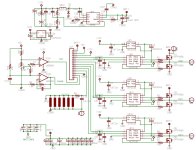
I've updated the image and Eagle files in the previous post (4 posts back, on Page 22 of this thread). Maybe this is not the kosher way to make updates, but it saves the littering of file versions throughout a thread. I think these are ready to for print. I'll probably get 6 PCBs made. If you want a PCB, send me a PM.

I'll upload a parts list soon.
Mark.

PS. Man, this takes the 'Simple' out of Simple BLDC Controller.
Just bumping this thread in hopes someone will post that they completed one of these BLDC controllers (original or modded) or knows someone that did. Maybe someone has gone on to mod this original design & made some improvements too?

Jeremy is off ES not actively posting for now, since he is involved in building some kind of off-the-grid house or related project.

Does anyone know of anyone that has continued on with this BLDC project whether original or modded???

Please give an update to this thread or point us to a new thread of related interest. :mrgreen:

Thanks!!!
 
Jeremys Simple BLDC design is pretty solid, I think.
I made a few boards and tried to work a few designs for a good brain.
Jeremy was convinced that the MC13033 was a great chip. I tried several PIC implementations for a brain.

I finally realized that microchip make a chip specific for BLDC controller: 18F2431. I've worked up a brain to couple onto Jeremys brawn design, and it works ok, but it need to spend some time with the over-current detection circuitry. This stuff is hard to debug. I have been on a few test drives with the 18F2431 and Jeremy's brawn board.

MauiMart just bought my last PCB for the Simple BLDC Brawn. I'm hoping that he will report some good successes.

MauiMart says that the old files got trashed from the ES system.
So here are all the eagle files, schematic pic, and parts list. The boards fit nicely in to the enclosure you can see in this thread: http://www.endless-sphere.com/forums/viewtopic.php?f=2&t=25748
 

Attachments

  • Version1.0EagleFiles.zip
    69.3 KB · Views: 250
  • Brawn_1.0.jpg
    Brawn_1.0.jpg
    181.4 KB · Views: 3,450
  • Partslist3.xls
    48.5 KB · Views: 216
I finally got around to populating the "brawn" board I received from hardym. My test results along with commentary follow.

I began by connecting my "brain" board (PIC MCLV develpment board stripped of its blown FET's) to the power board. The PIC was running the software from AN1160 (sensorless BLDC commutation using closed PI loop). Since I had not populated the 12V DC/DC converter from hardym's design, I used a separate power supply for that. Upon power up everything worked as expected. I was able to spin two different motors with 24VDC, the stock Turnigy 80/100-130 and another 80/100 that I wound with 9 turns of #14 in wye configuration.

It was now time to build-up the DC/DC and run another no-load test. Unfortunately the DC/DC was not able to provide enough output current for both the power board and the logic board so I powered the logic board separately again using a power supply. Again, both motors spun up nicely under no load.

[youtube]8TMRn5TOvIA[/youtube]
http://www.youtube.com/watch?v=8TMRn5TOvIA

The next phase was to step up the voltage using a 12s LiPo pack and apply some loading. I used a 30x12 prop attached to the stock Turnigy. At WOT I was seeing 48 battery amps @ 43V (2064W). You can see this run-up in the following video. I measured the temperature of the FET's and the low-side (non PWM) FET's were warmest at about 60C. The PWM duty cycle was only at 62% at WOT and I'm not sure why. I'll have to look at the software more closely. Nonetheless I was encouraged by the performance of the "simple 6-FET controller". The power in of 2kW is right around what I would need from this motor for my next bike - 3kW would be ideal.

[youtube]Rj0mz2glt7c[/youtube]
http://www.youtube.com/watch?v=Rj0mz2glt7c

Things were progressing nicely and at this point you might guess what is coming...

Phase III was to run my rewound motor with a load (prop) at 18s. I put another 6s pack in series and began to power up to about 72V knowing quite well that the IRFP4368'S are rated at 75V, giving me 3V of overhead. Once again, all systems go. I began to slowly spool up the throttle and reached 29A @ 67V (roughly 2kW battery input power again). I spooled back down and took a look at the PWM scope traces and noted 74% duty cycle at WOT and roughly 2700rpm (commutation frequency of 311Hz divided by 7 pole pairs times 60 seconds - does this sound right?).

Following the scope analysis I decided to do another spool-up run and measure some FET temperatures. At this point I was feeling confident with the power board and I upped the ante by spooling up more briskly than I had with all the previous runs and that's when the magic smoke (and large sparks and flame) let go. Of course the video camera was not running for this...

I'm not sure why it failed but I have a couple of ideas. I should have stayed at least 25% below max Vds for the MOSFETS. Also I think I should not have pushed my luck with the software running in sensorless mode. Perhaps the traces on the board gave way before the FET's exploded? My next planned test prior to the catastrophic event was to install internal hall sensors into the rewound motor and reload the PIC with sensored code. All in all I think this design has promise. I'm a bit discouraged at this point but if I do continue to work on that elusive controller for the large turnigy outrunners I would consider a 12-FET (100Vds) design with the FET's and caps mounted on bus bars instead of a PCB. I would also add shunts or hall effect current sensors to each individual phase and have the uController shut down or throttle back during over-current situations.

Comments? Anyone else messing around with this design?
over

*EDIT*
I added a video of a sweep through of a PWM commutation cycle at full power, measured at the high-side gate. Note the 70% duty cycle.

http://www.youtube.com/watch?v=JxSm6bpQbI8
*EDIT*
 

Attachments

  • P1040983.JPG
    P1040983.JPG
    110.1 KB · Views: 3,414
  • P1040986.JPG
    P1040986.JPG
    111.4 KB · Views: 3,408
  • P1040992.JPG
    P1040992.JPG
    113.2 KB · Views: 3,414
  • P1050003.JPG
    P1050003.JPG
    101.3 KB · Views: 3,408
  • P1050004.JPG
    P1050004.JPG
    96.4 KB · Views: 3,414
  • P1050032.JPG
    P1050032.JPG
    74.5 KB · Views: 3,414
  • P1050014.JPG
    P1050014.JPG
    77.3 KB · Views: 3,414
Hi Mauimart,

As a silent observer I've been eagerly following development of this BLDC and I'm wondering why the thread has slowed to a crawl. In principle a 6 fet design with plenty of safety margin seems like the best way to go! I saw Jeremy post again & hope that you guys continue. As a mechanical guy I lack the background, otherwise I'd be happy to test & breathe the magic smoke if need be! :D

Best of luck & Thanks again!
 
Hi Mauimart,

That looks like some pretty serious brawn board damage there :shock:

Sensorless commutation seems to be a bit of a black art to me.

I have destroyed many $$$ worth of sensorless controllers in the past. Some motors they work well with, some they dont, and one loss of sync event can be all it takes to turn your power board to toast !


I hope you are able to continue your valuable work in this field, It is an area where we badly need to progress.

I wonder if a sensor driven brain, because of its relative simplicity, would prove to be a more reliable driver?

Keep up the good work!
Burtie
 
:( I think your hunch was well founded about running them so close to their maximum voltage rating. Once avalanche kicks in, all hell lets loose. Something that I seem to recall about MOSFETs is that the Vds(breakdown) figure has been very close, indeed, to what actually happens in circuits. In the days of bipolar power transistors, the transistors usually seemed very capable of going over the Vce rating. It was a fuzzier situation from what I recall.
 
Burtie said:
Hi Mauimart,

That looks like some pretty serious brawn board damage there :shock:

Sensorless commutation seems to be a bit of a black art to me.

I have destroyed many $$$ worth of sensorless controllers in the past. Some motors they work well with, some they dont, and one loss of sync event can be all it takes to turn your power board to toast !
I too have destroyed my fair share of sensorless controllers. My plan from the start was to get this thing working under sensored control. Unfortunately I did not have halls installed in my rewound motor when I began testing and at times I lack patience. The halls are in now but I'm short one power board. :x
Burtie said:
I hope you are able to continue your valuable work in this field, It is an area where we badly need to progress.

I wonder if a sensor driven brain, because of its relative simplicity, would prove to be a more reliable driver?
The same commutation logic board can easily handle hall sensor inputs. All I have to do is upload the appropriate code, configure some jumpers, and connect the halls. Unfortunately, it will be a while until I have another power board to test this on.
Martin
 
Anybody want to make me a couple of these bords to ship me???
 
I have one more empty brawn boards that mauimart exploded. I've been able to do some test drives on the brawn board, but I've not finished testing due to some personal distractions.

My intial tries with a brain using simple PIC chips was not working well. I switched to making a brain using a PIC18F2431, which is DESIGNED to run a BLDC motor (figure that!). This has worked much better on the bench, but i've not been able to work on this for awhile.

I also have a few of the harder to get parts, like the smt 12v switcher and inductor. They were a few dollars each if you want them.

This board fits in a BOX enclosure, which has enuf room for a brain of your choosing.

board alone is $25 incl shipping to BC. PM me with your e-mail, I'll send you a parts list..
 
hardym said:
I switched to making a brain using a PIC18F2431, which is DESIGNED to run a BLDC motor (figure that!)
I just ordered a couple of these what do you think the max e-rpm we can run them at is?
 
Arlo1 said:
hardym said:
I switched to making a brain using a PIC18F2431, which is DESIGNED to run a BLDC motor (figure that!)
I just ordered a couple of these what do you think the max e-rpm we can run them at is?

Haven't explored its limits, but that PIC should be all you'll ever need to run a sensored drive, erpm-wise. I was using its smaller brother - the PIC16F690 - on my bike at 14,000 rpm with one of the smaller Turnigy outrunners. That's almost 100k erpm, and the 16F690 is limited to half the CPU clock speed of the PIC you're referring to.

BR/Mattias

(14,000 rpm with a 1:38 reduction :))
http://www.youtube.com/user/i95matra?feature=mhsn#p/a/u/2/JCQjhLfQIvo
 
incememed said:
Arlo1 said:
hardym said:
I switched to making a brain using a PIC18F2431, which is DESIGNED to run a BLDC motor (figure that!)
I just ordered a couple of these what do you think the max e-rpm we can run them at is?

Haven't explored its limits, but that PIC should be all you'll ever need to run a sensored drive, erpm-wise. I was using its smaller brother - the PIC16F690 - on my bike at 14,000 rpm with one of the smaller Turnigy outrunners. That's almost 100k erpm, and the 16F690 is limited to half the CPU clock speed of the PIC you're referring to.

BR/Mattias

(14,000 rpm with a 1:38 reduction :))
http://www.youtube.com/user/i95matra?feature=mhsn#p/a/u/2/JCQjhLfQIvo
Im planning for ~100,000 erpm! Collossus is 10 erpm per rpm and I plan to run it ~150 volts & Its a 75 kv motor!
 
OK, should be a walk in the park for your PIC.

Homemade controller tuning burns a lot of FETs (I think you know), so just make sure you are well protected. Do NOT rely on the processor Analog-to-Digital Converter for emergency overcurrent protection, it will never be fast enough.

Consider having a comparator sniffing the shunt/sensor voltage continuously. The output of this comparator should be connected to the highest priority interrupt on your processor. This interrupt routine should open all FETs, and keep them open. This way you'll have <10us fault clearing, and your FETs will almost always survive.

Implementing this is fairly straightforward for anyone who made the rest of the code, it may already be in there, just wanted to give heads up for a trouble free tuning period.

BR/Mattias
 
incememed said:
OK, should be a walk in the park for your PIC.

Homemade controller tuning burns a lot of FETs (I think you know), so just make sure you are well protected. Do NOT rely on the processor Analog-to-Digital Converter for emergency overcurrent protection, it will never be fast enough.

Consider having a comparator sniffing the shunt/sensor voltage continuously. The output of this comparator should be connected to the highest priority interrupt on your processor. This interrupt routine should open all FETs, and keep them open. This way you'll have <10us fault clearing, and your FETs will almost always survive.

Implementing this is fairly straightforward for anyone who made the rest of the code, it may already be in there, just wanted to give heads up for a trouble free tuning period.

BR/Mattias
Very good info thank you. For testing I have some SKM400GAL12E4 IGBT's comming for a good pirce and they have a "high short curcuit protection" So it would be nice if I can build a bad ass controller with them.
 
I agree with incememed. Make sure that you are measuring phase current in at least two of the legs for the ability to shut it down in over-current situations. You could use a shunt or hall-based Allegro type current sensor - I believe the response time is good enough and it provides isolation from the power board. I should have added this capability to the board I blew-up from hardym. The PIC18F2431 should be able to handle erpm of the collosus.
over
 
incememed said:
Haven't explored its limits, but that PIC should be all you'll ever need to run a sensored drive, erpm-wise. I was using its smaller brother - the PIC16F690 - on my bike at 14,000 rpm with one of the smaller Turnigy outrunners. That's almost 100k erpm, and the 16F690 is limited to half the CPU clock speed of the PIC you're referring to.

BR/Mattias

(14,000 rpm with a 1:38 reduction :))
http://www.youtube.com/user/i95matra?feature=mhsn#p/a/u/2/JCQjhLfQIvo

Just checked out your video - that's one fast spinning outrunner. Would you care to share any additional details on your home made controller? Which FET and how many are you using? What type of gate drive circuitry? Is the power board isolated from the controller board? What kind of heat are you generating at 2kW? BTW I think the cycle analyst uses the PIC16F690. Maybe we could request BLDC commutation in the next CA revision. :D
Thanks.
Martin
 
I have used a 6 FET, TO-247 size power stage. Drive current paths laid out as alu busbars. A current sensor where the battery connects.

FETS and gate drivers were considered the most fix parts of the design, they were put on PCB. 12V and 5V supply and processor were put on breadboard. They communicate through the thick grey wire.

View attachment 3
View attachment 2
View attachment 1


This power stage has been through one sensored drive development, advanced timing experiments and one sensorless drive development, and has seen its share of smoke, transplants and band-aid soldering. Some history:

- Whatever millimeters of drive current trace that weren't alu reinforced have melted, almost no matter how wide the trace.
- Melted traces led to the need to use the drain tab of the FET, hence the chopping up of the heat sink bar behind the FETs
- Somewhere along the electronics learing curve, the importance of proper bypass capacitors was unveiled. Such were retrofitted.
- Traces to the main caps burned up, these were instead screwed directly to the main busbar.
- Gate drivers have been replaced quite a few times, mostly due to 12V instability problems, but also due to shorted gates, connecting main voltage to the gate driver pin.

A well deserved retirement is in the pipe for this power stage. Next revision will include
- Onboard 12V and 5V conversions
- Thicker heat sink, with temp sensor
- Slimmer busbars stretching all the way to the FET.

Heat generated: Having the motor enclosed, this was a bit of concern, and a temp sensor was implanted in the motor onto the copper. It was set to trigger the fan at some 60C, and to trip the drive at some 100C. The fan came on quite frequently, but the trip level was never reached. The power stage gets warm to the touch. Nowadays I just leave the fan on, and don't monitor motor temp.

For any detail value, model, reasoning, etc, pls post.

BR/Mattias
 
Thanks for the update - nice, simple design. I especially like the bus bars bolted to the PCB. I was under the impression that you were monitoring phase current yet from the pictures and description it appears that you only use battery current to determine an over-current condition. Do you have plans to monitor phase current in your next revision? Also, what gate drive IC are you using?
Thanks.
Martin
 
No, I'm sticking with the ole
I_motor = I_batt / duty cycle
using the average battery current from the last few PWM-cycles, works fine for now. Too many other things with priority to worry about; gearbox update, making the chain stick for more than 10 min in rough terrain, refining the overcurrent protection, refining the sensorless startup sequence, exploring thermal and current limits of drive, allowing for freewheeling (motor standstill, rear wheel spinning) when throttle off, water and dust proofing. I'm still walking home from the trail 50% of the time... :x It's on the list, though.

Gate driver is IRS2186, to be used with a 4ohm gate resistor, which should produce peak charge currents way below rated value.

BR/Mattias

PS That's a very impressive motor wind in your sig!
 
OK so who wants to hold my hand and help me through the steps of programing the PIC18F2431 I will have it soon and I think I have everything on order I should need. So now is the time for me to read about programing and writing code.
 
Arlo1 said:
OK so who wants to hold my hand and help me through the steps of programing the PIC18F2431 I will have it soon and I think I have everything on order I should need. So now is the time for me to read about programing and writing code.

One of the reasons I got into this ebike building stuff is that I wanted to mess around with PIC processors
and wanted a cool application to put my PIC's in :D So ask away !

First step: download MPLAB from http://www.microchip.com/stellent/idcplg?IdcService=SS_GET_PAGE&nodeId=1406&dDocName=en019469&part=SW007002
and have a look at its manual. Do you have some sort of programmer like a PICKIT2 or (much better) a PICKIT3 ?
Also it's usefull to have a RS232 port on your computer (or some sort of USB<->RS232 cable) 'cause then
you can output data from your running PIC processor to your PC.

You know about hexadecimal and binary and stuff like that ?
 
Lebowski said:
Arlo1 said:
OK so who wants to hold my hand and help me through the steps of programing the PIC18F2431 I will have it soon and I think I have everything on order I should need. So now is the time for me to read about programing and writing code.

One of the reasons I got into this ebike building stuff is that I wanted to mess around with PIC processors
and wanted a cool application to put my PIC's in :D So ask away !

First step: download MPLAB from http://www.microchip.com/stellent/idcplg?IdcService=SS_GET_PAGE&nodeId=1406&dDocName=en019469&part=SW007002
and have a look at its manual. Do you have some sort of programmer like a PICKIT2 or (much better) a PICKIT3 ?
Also it's usefull to have a RS232 port on your computer (or some sort of USB<->RS232 cable) 'cause then
you can output data from your running PIC processor to your PC.

You know about hexadecimal an binary and stuff like that ?
LOL nope. I played around a bit with code for my megasquirt2 a couple years ago. But now its time to do the real lerning. I will read and download that all in the morning. I don't have a programer yet but.... Can we build it too? I maybe in over my head but I always find my way to the top. I am done with trying to reverse engineer some china controller its time to build my own!
 
Arlo1 said:
LOL nope. I played around a bit with code for my megasquirt2 a couple years ago. But now its time to do the real lerning. I will read and download that all in the morning. I don't have a programer yet but.... Can we build it too? I maybe in over my head but I always find my way to the top. I am done with trying to reverse engineer some china controller its time to build my own!

About binary and hexadecimal, this should be enough of an intro:
http://www.swansontec.com/binary.html

I build my own programmer but it's not something I want to do again. The issue is that each PIC processor is
different as far as the programmer is concerned, PIC12F needs a different sequence from a PIC16F etc etc.
So every time I wanted to use a new type of PIC I had to re-write my programmer, I got totally fed up with
this.

A PICKIT2 is a low cost programmer: http://www.microchipdirect.com/productsearch.aspx?Keywords=PG164120
but I wouldn't get that one as it can only program 5V PIc's (afaik).
The more advanced stuff runs on 3.3 V for which you need a PICKIT3.
You can get just the programmer: http://www.microchipdirect.com/productsearch.aspx?Keywords=PG164130
or combined with 12 lessons on programming in assembly: http://www.microchipdirect.com/ProductSearch.aspx?Keywords=DV164131

Oh, I don't know anything about programming this stuff in C, I only use assembly. What language do you intend to use ?
 
I've used C just a bit before but I really don't care what I use I just need to learn what I can, this has been something holding me back for a long time from my projects.
Thanks for all the links now its time to read them over my morning coffee. I found you can get knock off china Pickit3 programmers for ~$30 and the real thing for ~$50 so that's not to bad considering Ive blew up well over $500 worth of electronics so far on collossus.
 
Back
Top