Simple BLDC controller

I just proofed both board trace progs. nothing in there calling for an offset or any Jazz. (welcome to the world of open loop controll BTW :| )
Luke I sent you a copy of the codes direct with feed rates a bit slower than the progs on pg18. re down load the code on pg 18 & try try again.

I assume you are just setting X & Y "home" somewhere close & on the board....what are you doing to home Z? touching off or are you eyballing it?
have you run any diagnostics to determin your max acceleration rates.....also i have found to cut accurate arcs & corners feed rates need t be kept at the low end of the range....steppers don't stop on the dime like an real servo set up will.
if your running a hacked version of Mach3 I wonder if your getting a glitch passing the 250th line (trial version max) of code & getting a "bump".

last, put some calipers on the pc boards themselves.... are the dead flat? or slight bulge here or there?

maybe just drill one & we, laserjet & etch em from there.....
 
Missing a step or two would probably be unnoticeable in a PCB. Your res is certainly better than .001" per step. There has to be something else going on...
 
texaspyro said:
Missing a step or two would probably be unnoticeable in a PCB. Your res is certainly better than .001" per step. There has to be something else going on...


It seems to be off by roughly 0.022" at the exact moment it has the error! That's like a boatload of whole steps, and my controller does like 1/500th micro-stepping (or something like that), so something has to actually be telling it to stick down into the PCB.
 
Can you single step through the gcode and see where it barfs? Or do you have a preview/simulate option? Or can you try running your mill on EMC (linuxcnc.org)?
 
Could it be caused by a minute roughness or bearing lash on a lead screw? I know squat about programming so my analysis is based on the premise "If you only have a hammer every problem is a nail"
 
I took a look thru the gcode text file, but never having done any CNC stuff and not knowing what kind of stuff I'm looking for I can't see anything obvious.

I can figure out what some of the stuff is supposed to mean just by looking at it, with the axes labelled clear enough, and assuming the numbers after each one are specific distances it's supposed to move along or specific coordinates it's supposed to move to.

Assuming that, then the only lines that could cause Z axis changes would be those that actually specify such with a Z number, right?

If so, that narrows it down to only a very few places it could change at. I wish it had line numbers so I could just specify what they are, without each person looking at it counting the lines themselves. :(

There are a few Z positions at the beginning, which are Z0.25 for the first two, and Z-0.015 for the last of those. Then about 1/8 of the way down there's one for G00 Z0.25, and two lines later one for G01 Z-0.015 F 25. This repeats for a while, presumably as the tool is pulled up at the end of different cuts and moved to the next ones.

At the very end is another G00 Z0.25.

There are no other Z commands being issued, unless something else other than Z can change that axis, and all the others are in pairs so if they are relative rather than absolute, they can't be accidentally creating an offset by missing a reverse command or something.

So my best guess is that there is something else in this Gcode that the software being used on LFP's machine is incorrectly interpreting as a Z down command, but I have no idea what that would be.
 
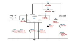
Iv been thinking a bit about adding a 12v supply and found what I belive is a nich device from national. Their online desingtool suggestes this circuit for 22-95v input and 12v 0.4A output:lm5008.png

Would this work? Any changes to make it work better in a e-bike environment?
 
That little switching regulator should work fine as a wide range 12V regulator, nice find. There's plenty of spare real estate on the "brain" board to add it, too.

Jeremy
 
0.4A is fine, as the FET drivers only deliver very short duration high current pulses to the FET gates, with a very low duty cycle. These high current peaks are delivered by the reservoir capacitors, so the continuous power drain on the 12V supply is less than 100mA.

Jeremy
 
There has been a lot of discussion about how to make "Brawn" PCBs. I know nothing about CNC, but i have had many PCBs made from PCBCart, direct from china. Takes a couple of weeks but the quality is good.

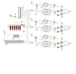
I put Jeremy's schematic into Eagle, so it looks a little different:
Schematic-v0.5.jpg
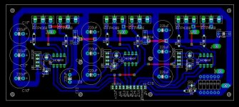
And here is what the one sided layout looks like
file.php

Layout-orig-v0.5.jpg

To get these one sided 2.65" x 6.3" made from china would cost $37 tooling, $6 each at quantity of 10, plus about $20 shipping, for 2oz copper.

However I dont know of an enclosure that will fit this size card.

Proposed enclosure is a Hammond extruded aluminium Box:
http://www.hammondmfg.com/pdf/531612.pdf
This enclosure has enuf room for both brawn and brain.

Here is the new layout for this hammond box, which is a bit bigger.
View attachment 2

The 3.53" x 5.8" two sided layout has a header for a separate brain board, but this one board is big enuf for both brain and brawn, either jeremy's MC33033, or the alternate brain under development (http://endless-sphere.com/forums/viewtopic.php?f=2&t=24519). Price from this from china (2oz copper) is $45 for tooling, $6.50 ea qnty of 10, and $20 shipping.

Here are the origional size eagle files. The file is really a zip, and must be renamed after you download.
View attachment Original_size_brawn_Files.zip.pdf

Mark.
 
That's nice work, should be useful for those who don't want to do the DIY board thing.

The only thing I'd change are all the high current tracks, these need to have as low an impedance as possible, and be beefed up with extra copper or wire, so all the track sizes leading to the FET S and D pins, plus the tracks going to the commutation capacitors and the phase and power connections need to be made a lot wider. In particular, pad space around the phase outputs and power connections needs to be big enough to take 10g wire comfortably, which means around 3mm diameter holes in the centre of those pads. The phase and power interconnect links are made from solid 2mm diameter copper wire on my prototypes, so again those pads need to be a bit bigger, too. Getting as much copper on the board as possible was one of the challenges with the original layout, I found. I ended up drawing outlines at the extreme periphery of each track and then flood filling to get maximum copper on the board, but I'm not sure if Eagle allows this. There will be peak currents of over 150A, being switched at sub uS times, flowing through some of the big tracks, so getting the impedance down is critical, particularly to the commutation capacitors.

I can't tell for sure, but it looks as if the 1uF film commutation capacitors might have the wrong pin spacing. These are fairly big capacitors but they look a bit small on that layout. Also, the capacitor labelled C10 isn't a 220uF any more, I had to change in in the final revision for a small 0.1uF ceramic, so that I could fit the brain board OK.

Jeremy
 
I have 3 spare chips for this project, If anyone wants one pm me your address.
 
liveforphysics said:
Thank you for the link Thud. I might get one of those, but I saw proof last night that I CAN do a perfect board with my machine setup, it's just a matter of getting all the different setup things correct on the same pass, and I will be set. I will figure out the right setup, and we will be set. :)

It's strange how a little thing like tool height, something that doesn't seem like a challenge at all, can be such a PITA.


Texaspyro- I'm thinking the same thing. The jig/fixture will be a block of aluminum with a star-burst pattern of channels in the bottom underneath where the PCB sits, a hole drilled part way down in the middle at the center of the start burst, then an intersecting hole drilled into the side, with a nipple threaded into it that will connect up to a high-volume vacuum pump that I've got. Should make for some solid securing force, and warped board straightening force.

LFP;
I piece of pegboard on a box is a quick and dirty suck-clamp. Just tape over the holes you don't need for a particular job.
 
It tends to bow under vacuum... we are trying to keep the thing flat to a couple of thou...
 
liveforphysics said:
texaspyro said:
Missing a step or two would probably be unnoticeable in a PCB. Your res is certainly better than .001" per step. There has to be something else going on...


It seems to be off by roughly 0.022" at the exact moment it has the error! That's like a boatload of whole steps, and my controller does like 1/500th micro-stepping (or something like that), so something has to actually be telling it to stick down into the PCB.

You might try slowing down the acceleration on the Z axis. I have experienced losing Z steps when running gcode that had back to back Z transitions. Jogging and most cutting worked fine, but ever so often I lost steps until I lowered the acceleration.

If you board is not larger than 5" in the Y direction and 10" in the X direction, I could run your code and see if I experience the same problem. I have a Taig and am running Mach.

Bubba
 
I made a discovery! My power supply to my steppers was cranked way down. Running 36v steppers at 12v. We set it there when I was first learning the machine so it hopefully wouldn't hurt itself when I would crash the spindle. Lol
 
hardym said:
There has been a lot of discussion about how to make "Brawn" PCBs. I know nothing about CNC, but i have had many PCBs made from PCBCart, direct from china. Takes a couple of weeks but the quality is good.........

Mark.

Thats awesome! Could you post the eagle file?

thanks!
 
*** UPDATED ***
The files below have been updated to reflect the great review comments. Hopfully this is ready to go.
*******************

I've reworked the basic "Brawn" schematic to include both a 12V switching supply (lm5008), a 5V supply and a current sensor amplifier. I think all of this will be needed for a good brain. The board has been sized at 6.3"x3.1" for a specific box: a B4-080BL from Box Enclosures available from several in several colors, and with mounting feet, from Allied & Newark:
http://www.boxenclosures.com/category/product_details.html?product__id=196005

FETS will mount to a heat sink copper bar, then to the front screw on-panel. Additional heat fins can be added to the outside of the box. If needed, the TO220 5V regluator can be screwed to the side wall.

There should be ample room for a "Brain" mounted on a small daughter board inside the box.

Here is a pic of the layout:
file.php

View attachment e-bikebrawn-Box.0.8i.brd.jpg

Here is the schematic:
View attachment Schematic.0.6.jpg

Here are the eagle files. As before, they are in a ZIP file renamed as a pdf. Download, save, and rename to a ZIP file
View attachment Eagle-e-bikebrawn-Box.0.8i.zip.pdf

Comments appreciated.
Mark.
 
Nice work, Mark.

Will the brain board still sit on the board at right angles on that layout? I ask, as I had to remove the 220uF capacitor at the bottom left of the board to get room for the connectors (I replaced it with a small ceramic). I found that vertical board space was tight over on the left of the board.

Also, the commutation capacitors on the left have long tracks and the other commutation capacitors are linked with tracks that are a bit thin. These really need flooded areas of copper with as low a track inductance as you can get. Ideally, you want to leave pretty much all the copper on this board wherever there are power tracks, as the peak current that will be flowing around those areas will be over 100A. I used extra 2mm copper links across the top surface of the board to hook up the "dead ends" of the commutation capacitor tracks, simply to lower the impedance at this point. With a double sided board you can add top surface copper with lots of PT vias to achieve the same effect.

I'd suggest making the power tracks much wider, as I mentioned previously. This is a controller that's around 3 or four times times more capable than the XieChang controllers of the same size, so needs really big power tracks, with additional copper soldered on afterwards. Now you've opted to go double sided I'd try and keep as much copper on both sides of the board as you possibly can. Etching copper off that could be usefully lowering inductance and increasing power supply decoupling capacitance isn't generally a good thing for a high current board like this.

What are the extra 100k resistors for on the driver inputs? It works fine without them, so I can't quite see why they are there, especially as the NCP5181 has internal pull down resistors on its inputs already - the resistors you've added are just in parallel with them and don't seem to do anything except take up board real estate.

It looks like there's a +5V pin there now. What does that drive? The "logic" levels are 12V on this unit, and the throttle and Hall supplies come from the reference voltage on the controller board.

The 1uF MKF film commutation capacitors look like they will be a very tight fit. These are pretty large, low ESR, capacitors and I think they might be a struggle to fit in the space. I found it hard to get space to fit them.

The 220uF capacitors will need to be moved, as where they are you won't be able to get at the screws on the FETs to bolt them up to the heatsink. They are pretty tall capacitors, taller than the FETs, so need to be fitted in vertical rows as far from the centre line of each FET as you can get them. My layout was less than ideal in this respect, as I had to angle a screwdriver to get at one or two of the FETs as I couldn't quite get them far enough away yet still maintain that critical low inductance connection to the power buss.

Overall it looks OK though. I found I went through around a dozen iterations before I got the first layout that sort of worked and even then scrapped the first two boards because they needed rework!

Jeremy
 
Thanks Mark!, but it looks like there are just JPGs in the zip file. I would love to have the eagle files! Maximum-hackability

I can't blame you for the series gate drive resistors. Even if you populate them with 0 ohm resistors in the end, its nice to have a way to control the gate drive ringing if need be.
 
Jeremy wrote
Will the brain board still sit on the board at right angles on that layout? I ask, as I had to remove the 220uF capacitor at the bottom left of the board to get room for the connectors (I replaced it with a small ceramic). I found that vertical board space was tight over on the left of the board.
Thanks for the comments.
Your simple MC33033 brain may fit at a right angle. The enclosure has some height available for a small sideways brain. My concept is to also be able to use a PIC powered brain that will need a larger parallel daughter board. I have a working PIC brain, but need to make some changes there too.

Also, the commutation capacitors on the left have long tracks and the other commutation capacitors are linked with tracks that are a bit thin. These really need flooded areas of copper with as low a track inductance as you can get...
Thanks, I'll need to beef up the traces. My plan was to not put solder mask on any of the power traces, and solder heavy copper wire across each of the power traces.

What are the extra 100k resistors for on the driver inputs? It works fine without them, so I can't quite see why they are there, especially as the NCP5181 has internal pull down resistors on its inputs already
These were added for pulldowns in case the brawn wasn't well connected with a brain. I wasn't aware of the NC5181 internal pulldowns, so, yes, these can be removed.

It looks like there's a +5V pin there now. What does that drive? The "logic" levels are 12V on this unit, and the throttle and Hall supplies come from the reference voltage on the controller board.
There are a few extra brain interface pins. the MC33033 brain may not need a 5V line, but other brains may need this. I had the real estate, so I put a TO220 7805 regulator on the brawn. It does not need to be populated. I've added a BAT+ line to the connector so a brain could see the full pack voltage. There are 3 different current lines available: ISense off the shunts. A programmable comparator off the LM358, and a current sense amplifier also off the LM358.

The 1uF MKF film commutation capacitors look like they will be a very tight fit. These are pretty large, low ESR, capacitors and I think they might be a struggle to fit in the space. I found it hard to get space to fit them.
Agree, another good catch. A MKF that I can afford will not fit in the allocated space.
The 220uF capacitors will need to be moved...
Agree. I added more than the origional spec, as I wasn't sure how many could actually be fit. I'll try to move the Caps from infront of the FETs.

I plan on making a couple more iterations on the layout then getting a few made. If anyone wants a board I can get one for about $25. If the SMT LM5008 scares you, I can mount it for another $5. Let me know soon. Disclaimer: All of this is highly experimental, and there are no guarantees any of it will work.

Mark.
 
Thanks for all the great comments and the education on Caps. (I've never really understood why there are so many types of Caps).
I've updated the image and Eagle files in the previous post (4 posts back, on Page 22 of this thread). Maybe this is not the kosher way to make updates, but it saves the littering of file versions throughout a thread. I think these are ready to for print. I'll probably get 6 PCBs made. If you want a PCB, send me a PM.

I'll upload a parts list soon.
Mark.

PS. Man, this takes the 'Simple' out of Simple BLDC Controller.
 
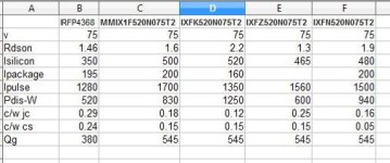
Here are some 75v FETs, package current limit for IXFZ520N075T2 isn't listed, it's got some fat leads compared to those little TO packages it seems.
Are any of those IXYS better than IRFP4368?

75v FET.jpg

IRFP4368 MMIX1F520N075T2 IXFK520N075T2 IXFZ520N075T2 IXFN520N075T2

Jeremy, you mentioned that the driver could probably drive 12 4368's. What about 12 of those IXFZ520N075T2 (if it actually is any better)?
Is there anything critical in the brain layout design, or can I just deadbug it?
Did you do any high current tests yet?

Can someone post a complete list of components?

Hardym, or anyone, do you have a set of boards left that I can buy?

Super duper effort on this project :)
 
Back
Top