Sur Ron lite bee
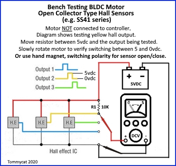
After some "urban trials" riding, I got a stuttering motor with low power. I thought I had partially shredded the primary belt and limped it home. Turns out the belt is in good shape. I tested other cut-off sensors and throttle on the bike and they are good. Testing the hall sensor I think I have found my problem but I want to double check before ordering a new one. Here is what I did -
Input voltage, (black and red wires) test at 4.0v. Advertised is 4.5v, but this may be OK as the battery is <50% charged?
One lead on the negative (black wire) and one on each of the phase wires:
Each phase wire (blue, green and yellow) does oscillate in output voltage, but only up to 0.6V. They were consistent in behavior across the lot, but I am assuming these values area too low and hall sensor needs to be replaced