liveforphysics
100 TW
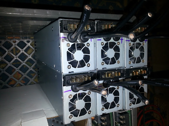
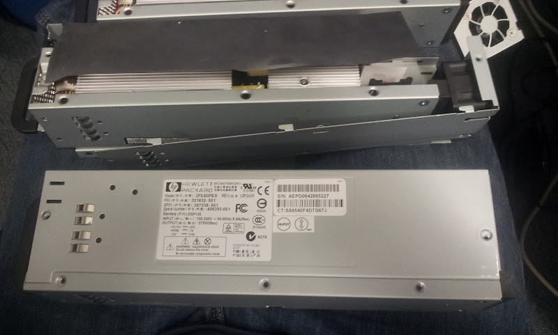
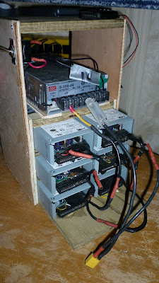
So, the little HP ESP-135 server supplies are dirt cheap, like $15-25 shipped sort of cheap. They must have a hundred bucks or more of materials and labor in each one, but the datacenter industry keeps the market flooded with used ones.
You can power an RC charger with them, or use them in series with a lab power supply or a CC-mode modified meanwell to be a battery charger. Putting them in series with something like a 20v 50amp lab power supply boosts the voltage so you can use it to charge something like a 18S LiPo pack for example. You would put 5 of these 12.65v output power supplies in series to give you 63.25v, then set the 20v 50amp lab supply to 11.25v and 50amps, and it would charge your pack at 50amps up to 74.5v (4.15v/cell), the server supplies would be a fixed voltage, and the lab supplies voltage would provide the current limiting and slowly climb to 11.25v as the pack charges.
This type of charging setup is fairly advanced, definitely something to try at your own risk after you've got plenty of experience and are comfortable with what you're doing. Otherwise just use them to power something like an RC charger, and let it handle the charging control.
Here is a video of the output being tested. They all seem to trip-off right about 56.x amps, so as long as you're not pulling over that amount of current, they just stay solidly fixed at about 12.4-12.65v depending on load.
[youtube]RHvGg64onnc[/youtube]
The power supply is a fully isolated type of architecture, but they intentionally tied the DC ground output to the chassis and AC ground in 2 places. Fortunately, these are pretty easy to remove from the DC side, which retains the AC chassis grounding, and allows us to run them in series while still retaining the AC chassis ground.
Remove the various chassis screws holding the sheet metal panels on and remove the top panel.
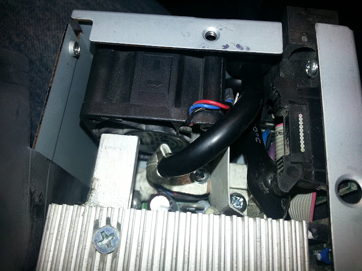
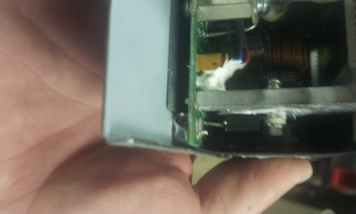
Pry the insulation layer's sticky goo adhesive off the other panel so it can be slid back from it's attachment slots. It will still be tied by the fairly short fan wires, so be gentle.
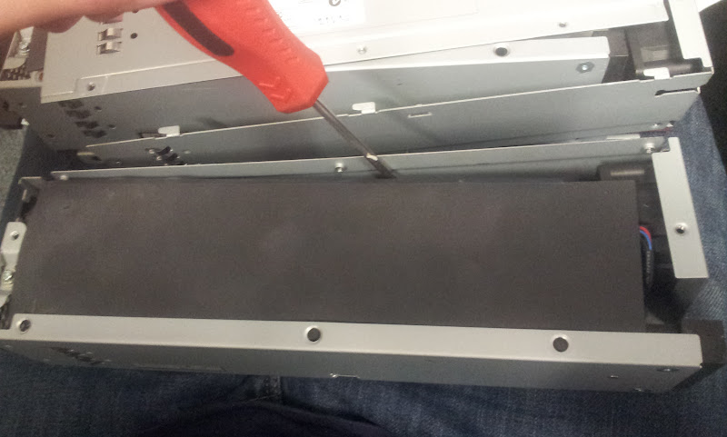
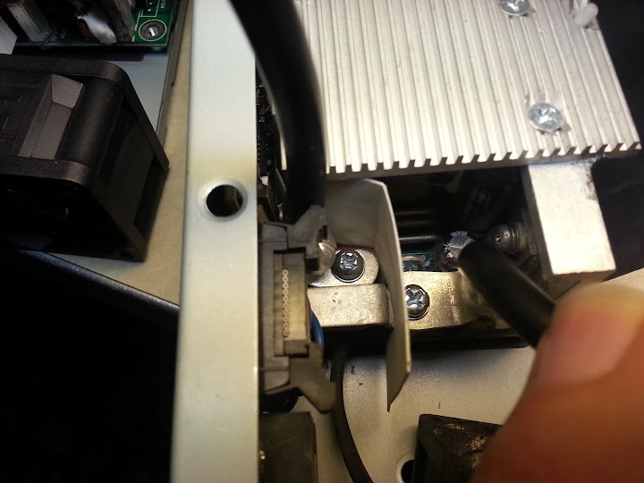
Remove that screw I'm pointing to. (all ready removed in picture)
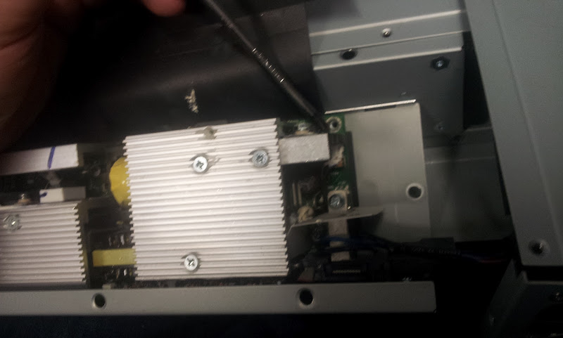
With that screw out, drill that pressed in nut out of the sheet metal from the back until the little stand-off body is free.
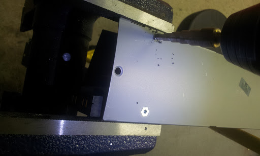
Pry the little stand-off nut you drilled out from under the board so that corner of the PCB is floating not contacting the chassis.
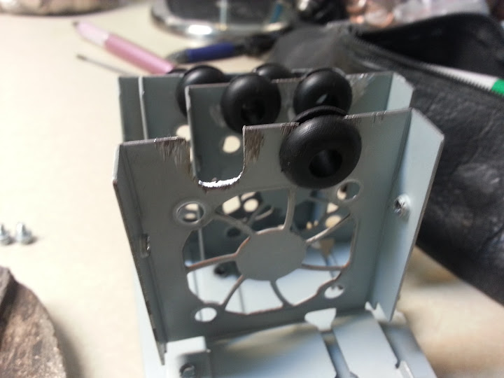
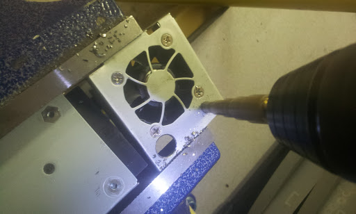
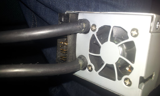
Drill a couple of holes in the sheet metal next to the fan sized large enough to fit your wires through. I used silicon 6awg wire (because it was laying around), I think 8awg would be fine and you wouldn't need as large of holes.
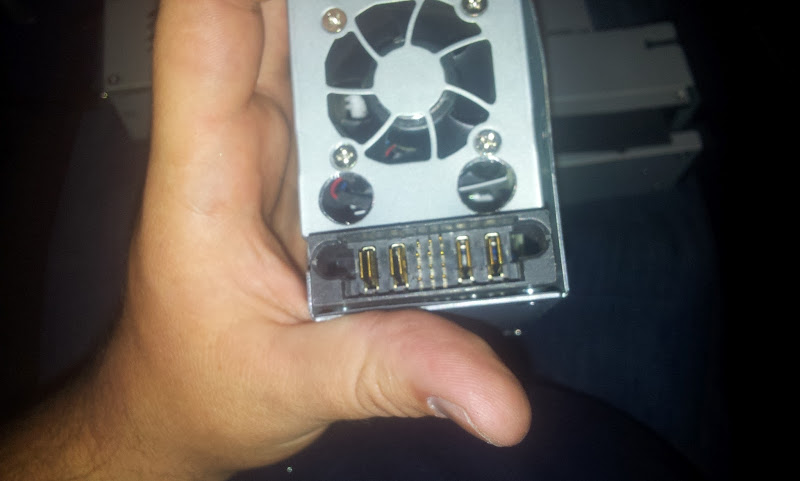
This is what the back of the supplies connector looks like. See that mess of pins in the middle? You need to connect just 3 of them together, and make sure the other pins are shorting to anything else.
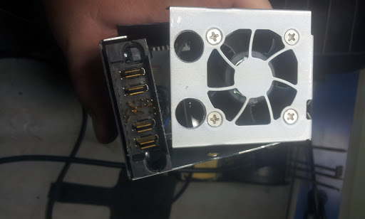
Now the three pins are bent so they are touching, and ready for a bit of solder. It's the lower left corner pin, and the middle two pins on the right side that need to be shorted together for the power supple to believe it's in a server and needs to power-on. Thanks to some RC groups guys for finding out which pins to connect to power these up.
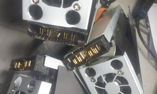
A few supplies with the pins bent and soldered.
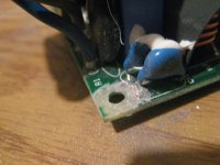
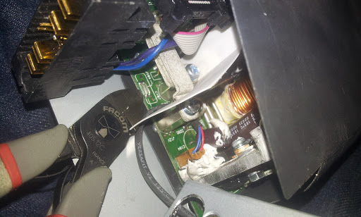
The PCB has 2 jumpers right where the tip of my dikes are pointing, you gotta snip them both and ensure you have no connection between those two sides anymore. This isolates the other point where DC was connected to the chassis.
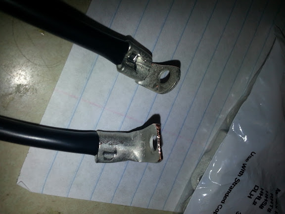
I crimped some ring terminals on and bent them to route decently from those two nice stand-offs. You can see my screw drive on one of the stand off screws you want to bolt one terminal on, the other is just down and to the left by a cm or two. These are the positive and negative output terminals of the power supply.
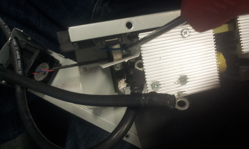
All bolted up.
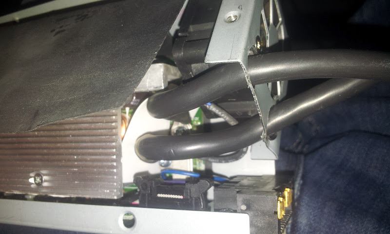
I slid some shrink around the wires in the area where they pass through the holes drilled in the sheet metal, just to help avoid it cutting the insulation and shorting. If you wanted to do it right, a grommet would be a good idea.
That's about it. It took me about 3hours of fooling around to do the first one and figure out how to isolate them and how to cable to them. Then doing 3 more of them took about 2hours of medium-easy work.
I would rate it about a 3 out of 10 on a DIY difficult scale. I would rate a 9.5 out of 10 on a value in power supply vs money spent scale.")
-Luke
You can power an RC charger with them, or use them in series with a lab power supply or a CC-mode modified meanwell to be a battery charger. Putting them in series with something like a 20v 50amp lab power supply boosts the voltage so you can use it to charge something like a 18S LiPo pack for example. You would put 5 of these 12.65v output power supplies in series to give you 63.25v, then set the 20v 50amp lab supply to 11.25v and 50amps, and it would charge your pack at 50amps up to 74.5v (4.15v/cell), the server supplies would be a fixed voltage, and the lab supplies voltage would provide the current limiting and slowly climb to 11.25v as the pack charges.
This type of charging setup is fairly advanced, definitely something to try at your own risk after you've got plenty of experience and are comfortable with what you're doing. Otherwise just use them to power something like an RC charger, and let it handle the charging control.
Here is a video of the output being tested. They all seem to trip-off right about 56.x amps, so as long as you're not pulling over that amount of current, they just stay solidly fixed at about 12.4-12.65v depending on load.
[youtube]RHvGg64onnc[/youtube]
The power supply is a fully isolated type of architecture, but they intentionally tied the DC ground output to the chassis and AC ground in 2 places. Fortunately, these are pretty easy to remove from the DC side, which retains the AC chassis grounding, and allows us to run them in series while still retaining the AC chassis ground.
Remove the various chassis screws holding the sheet metal panels on and remove the top panel.
Pry the insulation layer's sticky goo adhesive off the other panel so it can be slid back from it's attachment slots. It will still be tied by the fairly short fan wires, so be gentle.
Remove that screw I'm pointing to. (all ready removed in picture)
With that screw out, drill that pressed in nut out of the sheet metal from the back until the little stand-off body is free.
Pry the little stand-off nut you drilled out from under the board so that corner of the PCB is floating not contacting the chassis.
Drill a couple of holes in the sheet metal next to the fan sized large enough to fit your wires through. I used silicon 6awg wire (because it was laying around), I think 8awg would be fine and you wouldn't need as large of holes.
This is what the back of the supplies connector looks like. See that mess of pins in the middle? You need to connect just 3 of them together, and make sure the other pins are shorting to anything else.
Now the three pins are bent so they are touching, and ready for a bit of solder. It's the lower left corner pin, and the middle two pins on the right side that need to be shorted together for the power supple to believe it's in a server and needs to power-on. Thanks to some RC groups guys for finding out which pins to connect to power these up.
A few supplies with the pins bent and soldered.
The PCB has 2 jumpers right where the tip of my dikes are pointing, you gotta snip them both and ensure you have no connection between those two sides anymore. This isolates the other point where DC was connected to the chassis.
I crimped some ring terminals on and bent them to route decently from those two nice stand-offs. You can see my screw drive on one of the stand off screws you want to bolt one terminal on, the other is just down and to the left by a cm or two. These are the positive and negative output terminals of the power supply.
All bolted up.
I slid some shrink around the wires in the area where they pass through the holes drilled in the sheet metal, just to help avoid it cutting the insulation and shorting. If you wanted to do it right, a grommet would be a good idea.
That's about it. It took me about 3hours of fooling around to do the first one and figure out how to isolate them and how to cable to them. Then doing 3 more of them took about 2hours of medium-easy work.
I would rate it about a 3 out of 10 on a DIY difficult scale. I would rate a 9.5 out of 10 on a value in power supply vs money spent scale.
-Luke


.JPG")
s.jpg")