Mr. Mik
1 kW
- Joined
- Sep 3, 2008
- Messages
- 390
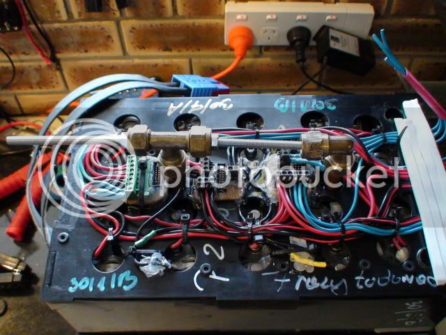
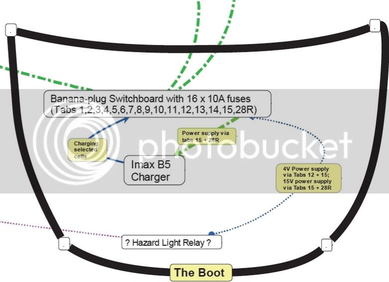
When I said:I came across a problem with the fuses I have soldered in line with the connector tabs:
The resistance of 2 x 20A fuses and cables and a single cell is too high to allow sufficient current to flow to open the fuse.
.....
......
I will need to test if 15A or 10A fuses would make a difference, but I suspect that their resistance might be higher and the same problem might occur - fuses not opening for a single-cell-short....
I was wrong, yippee!
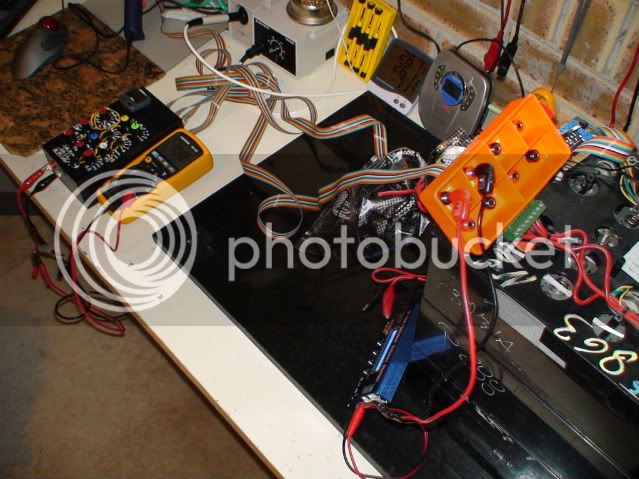
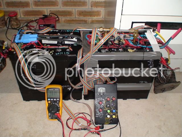
Today I soldered two 10A fuses together with cables and lugs etc, and then put 15A through them via the CBA2. The fuses blew immediately, one completely, the other one was a few microseconds behind but the fuse wire was obviously half-melted.
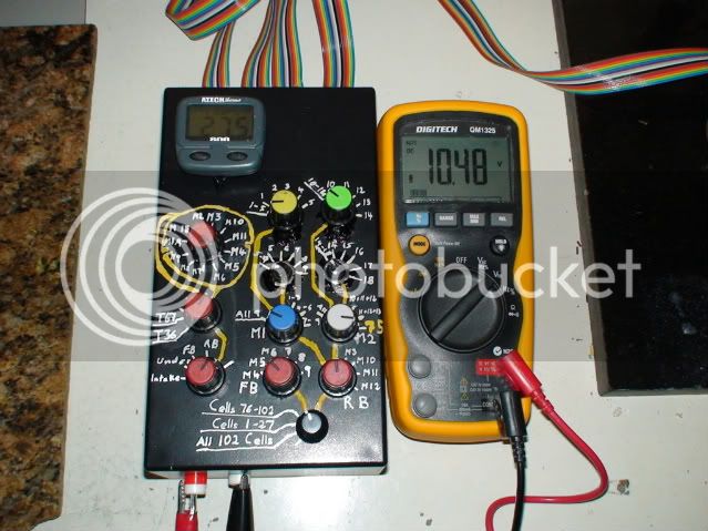
Then I did the same for two 15A fuses, started at 15A via the CBA2, increased the current stepwise until it hit the ceiling at 18.5A when I asked for 19A; same for 20A, of course.
This is exactly the same maximum current that the CBA2 achieved with 2 x 20A fuses in-line....hmmmmm....
So I decided to just short the cables together to see what happens! Of course, the fuse blew!
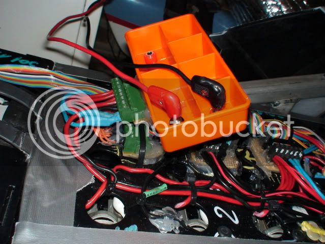
Next step: I soldered cable of excessive length to two 20A fuses, not soldered all too well, either...
Then shorted a single cell by screwing one fuse end onto the cell and holding the other fuse against the other battery pole, not a very good connection in other words; the cable ends were pushed into each other with fairly good contact, but not soldered.
Under these conditions one of the fuses blew after a few seconds, and the other one followed even quicker when I shorted the remains of this testing circuit across the cell!
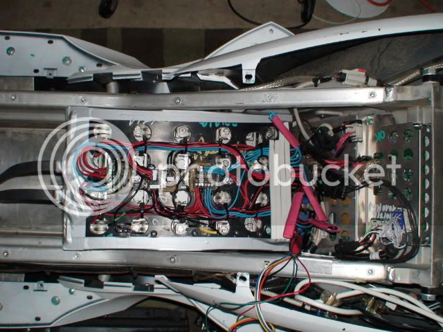
I believe this means that the 30A cable / 20A fuse set-up for the taps to the inter-cell-connectors will protect even single cells in a "short" situation.
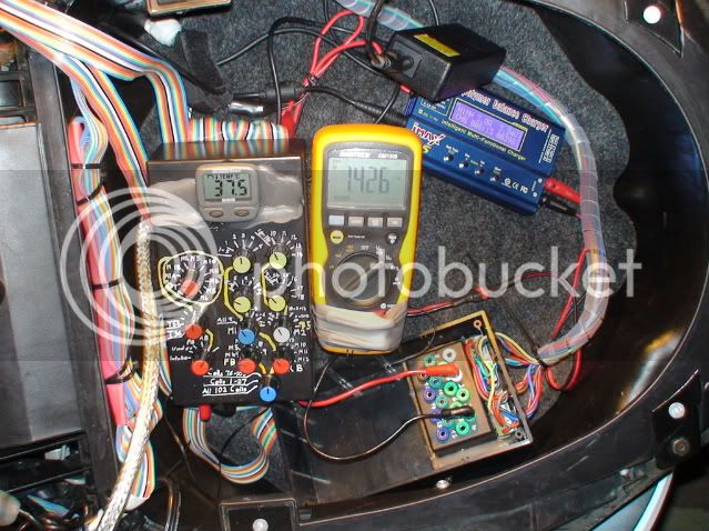
The current limitation to 18.5A experienced with the CBA2 was just an artefact caused by the internal resistance of the CBA2. Without the CBA2 the resistance is low enough to allow a single (charged) cell to blow one of the fuses.
There is only a small risk that a short could occur when the cells are already very empty and unable to melt the fuse wire. The cells would then remain shorted and get damaged, probably severely and permanently.