Vintage SLA "E⚡Wheels" Trike Info / Manual

0nelover

10 mW
Joined
Sep 22, 2023
Messages
25
Location
Gainesville FL
Hay Y'all!

Just joined up and hope you can help me get my trike back up and running!
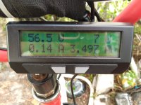
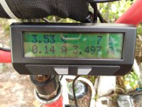
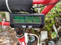
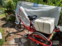
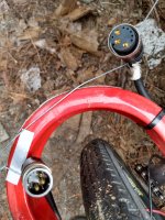
I recently bought a used Vintage SLA "E⚡Wheels" Trike. I am unable to find Info / Manual online. I can find current models of this trike and a lot has changed. My model has a Crystalyte rear hub motor of unknown wattage mounted in one of the 22" wheels, the front wheel is 20". An aftermarket "Grin Technologies - Cycle Analyst V3.1" has been installed combined with a "Baserunner L10 FTC" controller. This trike originally had four 12v SLA batteries in series for 48v 12Ah, and I upgraded to LiFePO⁴ 48v nomimal 20Ah. It ran fine for a couple weeks and then just quit yesterday after a very short taper of function and after recharge of battery still won't go. The Cycle Analyst (which incidentally I do have the rather complex manual for) is still functional and shows a motor temperature of 138*C the only reading that appears to be different than normal, it was ~100*C when I started the ride. I pray you can help me!

Thanks for Everything!
One Love, 0nelover
 
When you have the system turned on, press the left button of the CA to get to the Diag screen
1695439986834.png
Are any of the letters capitalized? Or are they all lower case?
 
T is a temperature limit, which makes sense with the reading you have. It means the CA is preventing operation because wherever the sensor is is too hot for it to operate, or the wires for the sensor are broken or shorted (or the sensor is failed).

Where is the temperature sensor in your system? (it could be in the motor, controller, battery, or separate external one)

A is an amps limit, which means too much current is flowing, so the CA is preventing operation to prevent overcurrent. If nothing is happening, no operation, and the battery isn't actually draining, it means there is something wrong with the measuring shunt or it's wiring.

The shunt could be a separate tiny box shape between the battery and controller, or it could be the one built into the controller.

Was there anything at all that happened or changed between the time it worked and the time it didn't? (no matter how insigificant it seems)
 
Hay amberwolf!

Significant changes just prior to fail? I was rather heavily loaded coming back from grocery shopping. The sound of the motor did seem a bit greater accompanied with a little more felt vibration. Nothing major just noticable at low speed loading and absent when a certain velocity was reached. The failure to function was brief perhaps a second or two, not instantaneous. Like one last spurt of energy.

The temperature sensor may very well be for the motor according to something I remember reading in the CA manual. The T reading has remained at 136*C and not returned to normal levels despite being idle so the read could be independent of actual temp. The battery I bought from BTRPOWER on Amazon, with separate charge and tap wiring only so likely no sensor there.

Shunts were discussed and described in the CA manual in some applications, I believe standalone shunt is absent.

CA does measure and indicate a small current draw of 7-8 watts for the display.

Note: The installer of CA included no shut-off switch so I have been powering down by unplugging the battery. I have made no settings changes to tailor to the present configuration thinking they would go to default in absence of power.

Thanks for Everything!
One Love, 0nelover
 
Significant changes just prior to fail? I was rather heavily loaded coming back from grocery shopping. The sound of the motor did seem a bit greater accompanied with a little more felt vibration. Nothing major just noticable at low speed loading and absent when a certain velocity was reached. The failure to function was brief perhaps a second or two, not instantaneous. Like one last spurt of energy.

The temperature sensor may very well be for the motor according to something I remember reading in the CA manual. The T reading has remained at 136*C and not returned to normal levels despite being idle so the read could be independent of actual temp.

Do you remember what the reading was while riding? If it was high, there may have been wiring or sensor damage from overheating.

Does the CA have the little JST plugs at the back accessible?
if so, unplug the temperature sensor two pin JST. The T limit will go away, but this is so you can test the sensor. If you have a multimeter, set it to ohms, and connect hte red and black leads to the two exposed pins or contacts of the wire you just unplugged from the CA (not the CA side, just the sensor side).

If the sensor is working, you will get a reading probably around 10kohms, that will change with temperature. If it's not, it could be any reading; post the reading here.


Shunts were discussed and described in the CA manual in some applications, I believe standalone shunt is absent.
Then it's using the one in the BR, whcih si a normal way of doing it.


CA does measure and indicate a small current draw of 7-8 watts for the display.
That's normal; it's probably measuring the total current of controller, CA, and any DC-DC for lighting or other things if there is one.

But if it says there's only 7-8 watts, then the amps should be very low, less than 0.2A. This shouldn't trigger an A limit flag.

So when you unplug the temperature sensor, check to see if the A limit also goes away (it shouldn't).


Note: The installer of CA included no shut-off switch so I have been powering down by unplugging the battery. I have made no settings changes to tailor to the present configuration thinking they would go to default in absence of power.

Thanks for Everything!
One Love, 0nelover
 
Hay amberwolf,

Checked JST connectors as instructed. Only three of the little plugs are currently utilized: Throttle, Brake and Auxiliary. The rest of the plugs are dangling: Thermistor, PAS/Torque, Communication and Power Out. The only other line out is the one for the controller itself.

For the sake of answering all your questions.... I noticed the start and current temperature reading as I reported above. 98*C and 138*C. The climb in temp read was gradual over ~1-2 hour. I suspect these values are spurious as the Thermistor doesn't appear to be hooked up to anything.

Thanks for Everything!
One Love, 0nelover
 
Checked JST connectors as instructed. Only three of the little plugs are currently utilized: Throttle, Brake and Auxiliary. The rest of the plugs are dangling: Thermistor, PAS/Torque, Communication and Power Out. The only other line out is the one for the controller itself.
If there's no connector used for the temperature sensor line, then that means it is probably using the WP8 direct-to-controller cable for this, with all the other CA signals (shunt +/-, power, ground, throttle out, speedometer, etc), then the motor-to-controller cable for the rest of the path.

That makes it harder to test, but not impossible. In this case there are two stages to the test, assuming it's using the WP8 connector (if it is osmething else, you'll need to tell or show us what it is). First disconnect the controller from the CA, and measure the temperature sensor pins as marked on this, for the controller side of the connection. It's the grey thermistor wire pin 4 to black battery ground pin 8.
1695610999168.png

If it reads that 10kohm or so varying with temperature (of the motor core), then everything between there and motor is ok, for that sensor.

If it doesn't read that, post what it does read. if you like you can also then measure the sensor wires at the motor connector of the motor itself, but I don't know what connector you have so I can't tell you which pins to check.


For the sake of answering all your questions.... I noticed the start and current temperature reading as I reported above. 98*C and 138*C. The climb in temp read was gradual over ~1-2 hour.

A gradual climb of that kind of temperature could be normal for a heavy load on the motor. Do you recall what temperature ranges you used to see before this problem?


I suspect these values are spurious as the Thermistor doesn't appear to be hooked up to anything.

Well, if it weren't hooked up at all, the CA wouldn't be programmed with any thermal limit and you wouldn't see the capital T indicating that limiting is happening. If it ends up being a failed sensor or connector, you can disable the limiting in the CA by going to this screen in the setup
1695611565246.png
and changing it to Disabled. You won't get any readings and teh CA won't limit anything based on that. If it still does, change the limiting settings to beyond what reading the CA still "sees" there.
 
Hay amberwolf,

Thank you for your patience with my vast ignorance.

I do have a digital multimeter although I cannot claim to be proficient in it's use. The reading I get for pins "4" and "8" is zero point zero. That indicates an open circuit, correct? True, measurement is more difficult, first off I had to hunt up a proper sized wire to probe with.

Attached you may find a photo of the multimeter on the setting I used and a photo of the connector between the controller and motor.

Thanks for Everything!
One Love, 0nelover
 
Hay amberwolf,

Err... I knew I was forgetting something important.
Here's the pix.
 

Attachments

  • IMG_20230925_113403611_HDR.jpg
    IMG_20230925_113403611_HDR.jpg
    2.5 MB · Views: 7
  • IMG_20230925_113324888_HDR.jpg
    IMG_20230925_113324888_HDR.jpg
    3.3 MB · Views: 7
Thank you for your patience with my vast ignorance.
The thing about ignorance is it is relatively easy to fix with time, effort, and patience. ;)

I do have a digital multimeter although I cannot claim to be proficient in it's use.

That is a classic. I used to have a Heathkit oscilloscope and ham radio transmitter/receiver pair until a decade ago or so.

To do the temperature sensor measurement with that meter, you would set it to Ohms, and 20Kohm or higher (so the center setting on the right knob, or any of the ones clockwise of that).


The reading I get for pins "4" and "8" is zero point zero.
Is this reading of 0.0 for the WP8 connector, or for the one you show in the picture?


Those pins are for the WP8 connector as shown in the previously-posted image of the connector on the cable between controller and CA. The connector you show in the picture is not a WP8 so I don't know which specific pin numbers those would be.


If it is the L1019 as ebikes.ca wires it then this diagram shows the wiring
1695671686040.png
and you would need to test on the motor side of that cable, between the ones marked as Black (Gnd) and Grey (Thermistor).


That indicates an open circuit, correct? True, measurement is more difficult, first off I had to hunt up a proper sized wire to probe with.
Zero is a short circuit (open circuit, or no connection, you can see the readout for by not touching the leads to anything), so the thermal sensor wiring is shorted together inside somewhere between the pins and the sensor itself. The sensors don't typically fail like that, so it's probably not the sensor itself, but something in the wiring.


If you don't need the temperature monitoring (if it doesn't normally get hot) then you can simply disable the limit within the CA as previously described.

If you do need the monitoring, you'd have to open up the motor to test if the problem is actually in the cable from connector to sensor, or at the sensor itself. If it's at the sensor, you can just replace the sensor (ebikes.ca carries compatible ones, and they can be had from many other places as long as you get the right model and resistance).
 
The thing about ignorance is it is relatively easy to fix with time, effort, and patience. ;)
True, ironically the more I emphasize knowledge the more ignorance gets drawn in with it. The more I know the more I know I do not and the more I doubt our ability to know anything. Lately I have been embracing ignorance to see if it will draw in knowledge!
That is a classic. I used to have a Heathkit oscilloscope and ham radio transmitter/receiver pair until a decade ago or so.
Yeah, the Heathkit multimeter may have reached it's expiration date I have just tried it on some known value tests and the readings are consistent and wrong. I have another meter that's MIA. I'll give looking for it another go tomorrow.
To do the temperature sensor measurement with that meter, you would set it to Ohms, and 20Kohm or higher (so the center setting on the right knob, or any of the ones clockwise of that).


Is this reading of 0.0 for the WP8 connector, or for the one you show in the picture?
Yes it was from the WP8 and maybe the multimeter is at fault.
Those pins are for the WP8 connector as shown in the previously-posted image of the connector on the cable between controller and CA. The connector you show in the picture is not a WP8 so I don't know which specific pin numbers those would be.


If it is the L1019 as ebikes.ca wires it then this diagram shows the wiring
View attachment 340052
and you would need to test on the motor side of that cable, between the ones marked as Black (Gnd) and Grey (Thermistor).
I tried this and no combination of any two pins produced a reading.
Zero is a short circuit (open circuit, or no connection, you can see the readout for by not touching the leads to anything), so the thermal sensor wiring is shorted together inside somewhere between the pins and the sensor itself. The sensors don't typically fail like that, so it's probably not the sensor itself, but something in the wiring.


If you don't need the temperature monitoring (if it doesn't normally get hot) then you can simply disable the limit within the CA as previously described.
How hot is too hot?
If you do need the monitoring, you'd have to open up the motor to test if the problem is actually in the cable from connector to sensor, or at the sensor itself. If it's at the sensor, you can just replace the sensor (ebikes.ca carries compatible ones, and they can be had from many other places as long as you get the right model and resistance).
I am willing, able is questionable. Good thing I am cultivating frightening myself daily to stretch the proverbial envelope.

I intend to hunt for the multimeter again tomorrow and if it's still MIA perhaps Harbor Freight has an inexpensive one that will serve.

Thanks for Everything!
One Love, 0nelover
 
True, ironically the more I emphasize knowledge the more ignorance gets drawn in with it. The more I know the more I know I do not and the more I doubt our ability to know anything. Lately I have been embracing ignorance to see if it will draw in knowledge!

Yeah, the Heathkit multimeter may have reached it's expiration date I have just tried it on some known value tests and the readings are consistent and wrong.

There is a calibration adjustment point (usually a tiny philips head potentiometer) between the lead connection points. The adjustment procedure should be in the manual attached here, page 42 (didn't read it, just looked at the index ;) ) :

Yes it was from the WP8 and maybe the multimeter is at fault.

I tried this and no combination of any two pins produced a reading.
If you have it set to ohms and get zero for every reading, what reading do you get for meter leads not touching anything, and what reading do you get for leads only touching each other?
How hot is too hot?
For a DD hubmotor, pretty hot is 120-150F, too hot depends but is usually somewhere up near water's boiling point. If you can't keep the back of your hand comfortably on the motor surface, it's probably overheating, for instance.
I intend to hunt for the multimeter again tomorrow and if it's still MIA perhaps Harbor Freight has an inexpensive one that will serve.
If they still carry this one, it works for basic tasks; it's not really super accurate but that doesn't usually matter. Just make sure to change the battery in it when you get it, since most of the ones I've run across were running low causing high meter readings.
There are much better ones out there, but it's probably about as good as the HK you have now depending on the care taken building the HK and the condition and tolerance of the parts inside, and will work for most kinds of testing needed for ebike and general electronics stuff for things that are worth fixing and easy to repair.

If you need something highly reliable and accurate and durable, Fluke makes good stuff (I have an ancient 77-IIIa) but they are expensive. If you need something that can do other testing types or greater range / more precision, etc., cost starts going up rapidly, to things like the DE-5000.
 

Attachments

  • IM-1210.manual.PDF
    5.6 MB · Views: 7
There is a calibration adjustment point (usually a tiny philips head potentiometer) between the lead connection points. The adjustment procedure should be in the manual attached here, page 42 (didn't read it, just looked at the index ;) ) :


If you have it set to ohms and get zero for every reading, what reading do you get for meter leads not touching anything, and what reading do you get for leads only touching each other?

For a DD hubmotor, pretty hot is 120-150F, too hot depends but is usually somewhere up near water's boiling point. If you can't keep the back of your hand comfortably on the motor surface, it's probably overheating, for instance.

If they still carry this one, it works for basic tasks; it's not really super accurate but that doesn't usually matter. Just make sure to change the battery in it when you get it, since most of the ones I've run across were running low causing high meter readings.
There are much better ones out there, but it's probably about as good as the HK you have now depending on the care taken building the HK and the condition and tolerance of the parts inside, and will work for most kinds of testing needed for ebike and general electronics stuff for things that are worth fixing and easy to repair.

If you need something highly reliable and accurate and durable, Fluke makes good stuff (I have an ancient 77-IIIa) but they are expensive. If you need something that can do other testing types or greater range / more precision, etc., cost starts going up rapidly, to things like the DE-5000.
 
Hay amberwolf,

Dropping back a step to regroup.

I found the MIA multimeter and am more confused unable to make head nor tails of the readings they render.

First the HK, going down through it, all display values are the same either open or shorted:
Left Knob (lk): Off
Right Knob (rk): 200 Ohms
Display (d): dark

lk: DCV 1000 max
rk: 200 Ohms
Display: Open - begins counting

lk: DCV 1000 max
rk: 2k Ohms
Display: Open - .01

lk: DCV 1000 max
rk: 20k Ohms
Display: 0.0

lk: DCV 1000 max
rk: 200k Ohms
Display: 00

lk: DCV 1000 max
rk: 2K 2M Ohms
Display: .00
_____________

Left Knob (lk): Ohms
Right Knob (rk): 200 Ohms
Display (d): Open - Over indicated, 85; Shorted - Over indicated, 87

lk: Ohms
rk: 2k Ohms
Display: Over indicated, .85; Shorted - Over indicated, .87

lk: Ohms
rk: 20k Ohms
Display: Over indicated, 8.5; Shorted - Over indicated, 8.7

lk: Ohms
rk: 200k Ohms
Display: Over indicated, 85; Shorted - Over indicated, 87

lk: Ohms
rk: 2K 2M Ohms
Display: Over indicated, .85; Shorted - Over indicated, .87

=================

Next the other one Cen-Tech 69096:
A photo because discription difficult.
The display is the same Open or Shorted.
IMG_20230926_120029860.jpg
I suspect both meters are kaput and I am the common denominator so "the error may be on the user side of the keyboard."

Please advise.

Thanks for Everything!
One Love, 0nelover
 
First the HK, going down through it, all display values are the same either open or shorted:
Just a note on how to measure:

Since you are testing ohms (resistance), then as I previously posted: "To do the temperature sensor measurement with that meter, you would set it to Ohms, and 20Kohm or higher (so the center setting on the right knob, or any of the ones clockwise of that)."

If you don't have it set to Ohms you can't test resistance, you are instead testing whatever other unit you set it to, and the range you are using on the right determines how much of whatever unit it is you have set it to. The manual for the unit (available online, as was the one I previously attached to a post) should show you the full procedures for each type of unit you wish to measure.

"over" means that whatever you are measuring is higher than the range chosen can measure. For resistance, that means taht since you've tested even on the highest range, it is open-circuit, or no connection.

If you get that on every pin of the WP8 connector to the controller, something is probably wrong with your meter leads.

Assuming the "shorted" readings you describe are when you touch just the meter leads together, then the meter leads themselves are probably broken, usually this is the wires inside them.

You can test which lead is broken by unplugging one, then poking the other one down into the hole to touch the metal contact. Whichver one then causes a response is still working.

If neither lead causes a response, another possiblity is that the fuse in the meter is blown. That previously-attached manual probably shows how to check that.

You can test if it's the fuse or just both leads by using a different piece of wire to connect from one meter hole to the other. If that gives a reading, the fuse is good and both meter leads are broken. If you still get no reading (as you have seen so far), then the fuse is probably blown, and you can follow the manual's procedure to check it / replace it.


=================

Next the other one Cen-Tech 69096:
A photo because discription difficult.
The display is the same Open or Shorted.
If the leads are being connected to the COM and VohmA plugs on the meter, and you see that 1 and a decimal point (that changes position with different knob positions indicating which range it's in), it means the same thing as "over" on the other meter (some meters use OL instead) and it's reading an open circuit, meaning it's fuse is blown or the meter leads are broken.

If this one's fuse is blown, it's probably harder to replace, as the meters I have like it are all soldered in...but it's still a regular glass fuse and you can still replace it.
 
If neither lead causes a response, another possiblity is that the fuse in the meter is blown.
Hay amberwolf,

Opened HK case and your diagnosis is correct an old school glass 3A fuse is toast. Leads visually seem intact. I will test them when I secure a fuse, all the ones I have on hand are the flat plastic modern automotive ones.

Thanks for Everything!
One Love, 0nelover
 
For a DD hubmotor, pretty hot is 120-150F, too hot depends but is usually somewhere up near water's boiling point. If you can't keep the back of your hand comfortably on the motor surface, it's probably overheating, for instance.
Thanks for the old school baby formula method of sussing out if it is too hot to continue trotting. (grin)
If you need something highly reliable and accurate and durable, Fluke makes good stuff (I have an ancient 77-IIIa) but they are expensive. If you need something that can do other testing types or greater range / more precision, etc., cost starts going up rapidly, to things like the DE-5000.

I shall endeavor to manifest a used one of higher quality and efficacy.

Thanks for Everything!
One Love, 0nelover
 
Hay amberwolf,

I secured a 3A fuse with some difficulty. My Ace Hardware is phasing out/away from carrying the old style 1.25" glass tube fuses. The only 3A fuse they had in stock was a "slo-blo" one. The package of two was $7.52, ironically comparable to the cost a new budget multimeter!

Fuse Installed I believe I am getting more accurate results. The pins for the Thermistor on the WP8 connector on the controller side are 0.0 as are the leads touching one another.

The other connector (L1019) on the motor side, I tested as well. The three big pins are the only ones that produce a change in multimeter reading. The center pin (yellow) tested for resistance on either of the adjacent pins (green or blue) was 0.0 as well.

Futzing about and exploring I discovered that the capital "A" in the error display goes to lowercase "a" when the brake lever is mashed and returns to uppercase "A" when released.

Thanks for Everything!
One Love, 0nelover
 
The pins for the Thermistor on the WP8 connector on the controller side are 0.0 as are the leads touching one another.

Wierd; that's a dead short, which you shouldn't read on any of the pins of the controller's WP8 connector.


The other connector (L1019) on the motor side, I tested as well. The three big pins are the only ones that produce a change in multimeter reading. The center pin (yellow) tested for resistance on either of the adjacent pins (green or blue) was 0.0 as well.

The big pins are the ones that should read zero ohms, as they are effectively a dead short, just coils of wire between each of them.

All the other pins should read either a medium to high resistance, or open-circuit.


Futzing about and exploring I discovered that the capital "A" in the error display goes to lowercase "a" when the brake lever is mashed and returns to uppercase "A" when released.
That doesn't make any sense either, because the brake lever couldn't trigger a current limit, unless you were actually moving and it engaged regen so that the current back from the motor / controller to the battery was higher than whatever limit is set in the CA. But this would be getting the A during braking, and the a when *not* braking...so...no sense at all?

What are the Amps showing on either the main screen, or the screen one right-button push over from the main screen, before you pull the brake lever, and during?
 
Hay amberwolf!

I haven't heard from you in a minute. I finally took the plunge and disabled the Temp sensor which did clear the T and A (no pun intended) error flags and restored function AFAICT just bench testing throttle activation.

Thanks for Everything!
One Love, 0nelover
Wierd; that's a dead short, which you shouldn't read on any of the pins of the controller's WP8 connector.


The big pins are the ones that should read zero ohms, as they are effectively a dead short, just coils of wire between each of them.

All the other pins should read either a medium to high resistance, or open-circuit.


That doesn't make any sense either, because the brake lever couldn't trigger a current limit, unless you were actually moving and it engaged regen so that the current back from the motor / controller to the battery was higher than whatever limit is set in the CA. But this would be getting the A during braking, and the a when *not* braking...so...no sense at all?

What are the Amps showing on either the main screen, or the screen one right-button push over from the main screen, before you pull the brake lever, and during?
 
Hay amberwolf,

The Amps reading on CA is zero on the diagnostic screen to the left of default screen. The Amps shown on the first screen is to the right of default is: "0.14 A"

I took the e-trike out to the Farmers Market yesterday (~ten miles round trip) on a test drive. It performed normally. I closely monitored the hub motor temperature by manually touching it as you recommended. It warmed slightly, so no issues there with standard operation.

Thanks for Everything!
One Love, 0nelover
 

Attachments

  • IMG_20231003_101951896_BURST004.jpg
    IMG_20231003_101951896_BURST004.jpg
    3.2 MB · Views: 1
  • IMG_20231003_101951896_BURST007.jpg
    IMG_20231003_101951896_BURST007.jpg
    3.2 MB · Views: 1
  • IMG_20231003_102034596_HDR.jpg
    IMG_20231003_102034596_HDR.jpg
    3.8 MB · Views: 1
I haven't heard from you in a minute.
Sorry, I try to help everyone every day but it's not always possible; I do this stuff here after my exhausting dayjob in the time I can't sleep. Last several days I haven't had as much time to do it since I have had my own trike problems with a broken motor axle, then some tribulations with the new motor wheel not working with the controller already on there, having to swap that out too, then the motor self-disassembling and grinding itself up inside:


I finally took the plunge and disabled the Temp sensor which did clear the T and A (no pun intended) error flags and restored function AFAICT just bench testing throttle activation.
Wierd that the temperature sensor would do anything to cause the current limit to activate. It shouldn't. (just as the brake lever shoudln't have anything to do with it).

Hay amberwolf,

The Amps reading on CA is zero on the diagnostic screen to the left of default screen. The Amps shown on the first screen is to the right of default is: "0.14 A"
What is the reading when the A limit shows up, as well as the reading when the A limit changes back to a? That's the important thing to know.

Whatever the reading is while it's capitalized (limiting), is what it's exceeding to cause it to limit, and so either the limit itself needs to be changed to reflect real-world needs, or the problem causing the excessive current draw needs to be fixed, or the CA's settings are simply corrupted and need to be redone.

If the last is the case, then the "best" way is to take pictures of every screen in every menu and submenu in the setup menu, reset the whole thing to factory defaults, and then manually re-enter every setting to be sure no data is corrupted.

If you have the PC-based setup program you can use that to back up the existing settings as well, then reset to factory, power cycle the CA, and then reset to factory, and then reupload the settings file to it. (if it's a corrupt setting it *might* be cleared by this, but if it saved that corruption it will just put it back....).


I took the e-trike out to the Farmers Market yesterday (~ten miles round trip) on a test drive. It performed normally. I closely monitored the hub motor temperature by manually touching it as you recommended. It warmed slightly, so no issues there with standard operation.
Sounds like it's working well enough, though it would be nice to know what's causing the wierd (impossible) stuff, so it doesn't unexpectedly cause you further problems later on.
 
Sorry, I try to help everyone every day but it's not always possible; I do this stuff here after my exhausting dayjob in the time I can't sleep. Last several days I haven't had as much time to do it since I have had my own trike problems with a broken motor axle, then some tribulations with the new motor wheel not working with the controller already on there, having to swap that out too, then the motor self-disassembling and grinding itself up inside:

I am grateful for Everything, bro. Also, I got this trike as backup / step up from a kit I put on a Schwinn Meridian so please consider me and mine of lower priority than people like yourself who fully rely on one egg basket. I often need to remind myself it is important to keep ourselves in the loop and not always be last one served at the buffet.
Wierd that the temperature sensor would do anything to cause the current limit to activate. It shouldn't. (just as the brake lever shoudln't have anything to do with it).


What is the reading when the A limit shows up, as well as the reading when the A limit changes back to a? That's the important thing to know.

Whatever the reading is while it's capitalized (limiting), is what it's exceeding to cause it to limit, and so either the limit itself needs to be changed to reflect real-world needs, or the problem causing the excessive current draw needs to be fixed, or the CA's settings are simply corrupted and need to be redone.

If the last is the case, then the "best" way is to take pictures of every screen in every menu and submenu in the setup menu, reset the whole thing to factory defaults, and then manually re-enter every setting to be sure no data is corrupted.

If you have the PC-based setup program you can use that to back up the existing settings as well, then reset to factory, power cycle the CA, and then reset to factory, and then reupload the settings file to it. (if it's a corrupt setting it *might* be cleared by this, but if it saved that corruption it will just put it back....).
The daughter handling the estate of the previous owner of my trike had only one manual and it was for the CA. Scrawled on the cover was the name of the local bike shop who installed the CA at least and I suspect the Baserunner controller and Crystalyte motor also. I have visited the shop and the mechanic I talked to seemed to have remembered the trike. I left my number and name, with no response yet. I want to see if I can get some clues from them about how they configured things, e.g. what model number the motor is &tc. I will keep your advice in mind when ready to proceed.

“Westheimer's Discovery: A couple of months in the laboratory can save a couple of hours in the library.”
-Frank H. Westheimer, chemistry professor (1912- )

Sounds like it's working well enough, though it would be nice to know what's causing the wierd (impossible) stuff, so it doesn't unexpectedly cause you further problems later on.
It is working beautifully as before this hiccup. I am reluctant to fix it until it's broken to satisfy our burning curiosity. <Grin> When I first retired and the Meridian was my sole ride and had a gas motor. I thought I should drop AAA. Then I called and asked them if I broke down on my adult tricycle would they come and help? They said, "Absolutely." A couple times now they have done. I tell them when I call what I need help with and they send a truck and trailer, load up the trike, strap it down securely and take me home with it. Real godsend for peace of mind.

Thanks for Everything!
One Love, 0nelover
 
Back
Top