throttle wiring question

puddleglum

100 mW
Joined
Mar 10, 2012
Messages
49
Location
Alberta, Canada
Hi guys,
I have a mobility scooter that I built for my son (pics are down in the scooter section) using parts from a stand up scooter. It has a 24v brushed motor and controller and a 3 wire hall effect throttle. in the diagram, wires are positive, negative,and signal I think. It is working well but the throttle cut in is quite aggressive and it is a little fast to be safe for use in congested areas. I would like to add a low speed circuit that could be switched on to limit throttle input when needed. Can it be done with this style of throttle? If it was a resistor throttle, I could just add a resistor, but could I do the same thing with this one? I don't really have a good understanding of how they work, which doesn't help. I know that trying to limit speed is the opposite of what most of you are trying to do, but if someone could tell me an easy way to do it, I would appreciate it. I don't really want to gear it down any more. It has lots of torque now, and it's nice to have the extra speed sometimes. I don't want the motor to have to run at full rpm all the time anyway.
 
I don't have a link to the threads, but there are a few people that have put resistor voltage dividers in the signal path, or other similar modifications, that should do what you want.
 
You can test with a 10K linear potentiometer. Join the red and black wires to the outer two pins and the signal wire to the middle one. When you turn it, motor speed will increase/decrease. Controllers normally want to see zero throttle before they give power, so you have to turn the potentiometer down first. You can sometimes get better response by putting a 1K resistor in series with the signal wire, but that's not necessary for testing.

You can use the pot as a speed control, and then use a separate switch on the red signal wire to activate it, so that you get motion when you press a button, and the speed depends on the potentiometer position.

Some stand-up scooter throttles work like a switch = on/off, so you might have the wrong type of throttle. Also, some work backwards, i.e. full power when shut and no power when open. You can only find the correct type by trial and error.
 
To smooth the throttle a bit I used this mod suggested by fechter:

http://endless-sphere.com/forums/viewtopic.php?f=2&t=37190&p=582952#p546409


It works pretty well with my controller.


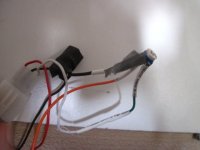
To limit the speed I am trying a potentiometer in addition to the previous mod. It works pretty well. The swipe is connected to the ground and the other two pins of the pot are connected to the signal wire going to the controller.
I am using a 2.2kohm pot but I think a 1k or 500ohm would work better.


IMG_0534.JPG
 
d8veh said:
You can test with a 10K linear potentiometer. Join the red and black wires to the outer two pins and the signal wire to the middle one. When you turn it, motor speed will increase/decrease. Controllers normally want to see zero throttle before they give power, so you have to turn the potentiometer down first. You can sometimes get better response by putting a 1K resistor in series with the signal wire, but that's not necessary for testing.

You can use the pot as a speed control, and then use a separate switch on the red signal wire to activate it, so that you get motion when you press a button, and the speed depends on the potentiometer position.

Some stand-up scooter throttles work like a switch = on/off, so you might have the wrong type of throttle. Also, some work backwards, i.e. full power when shut and no power when open. You can only find the correct type by trial and error.

I'm a little confused by this, sorry. Forgive me but I'm pretty much an idiot when it come to electronics. I definitely have a variable speed throttle though. Are you suggesting to replace the existing throttle with a 10k pot. and a on/off switch, or put the pot in parallel with the throttle and use a switch to engage it, or something else entirely?
 
spuzzete said:
To smooth the throttle a bit I used this mod suggested by fechter:

http://endless-sphere.com/forums/viewtopic.php?f=2&t=37190&p=582952#p546409


It works pretty well with my controller.


To limit the speed I am trying a potentiometer in addition to the previous mod. It works pretty well. The swipe is connected to the ground and the other two pins of the pot are connected to the signal wire going to the controller.
I am using a 2.2kohm pot but I think a 1k or 500ohm would work better.

That mod by fechter looks like a good place to start and should be in the range of my limited abilities. Just to be sure I understand what you did, you have the trim pot in series in the ground wire and the other pot in parallel with all three of the throttle wires?

Thanks for the help guys.
 
Hi puddleglum,

I've seen your build, awesome work!

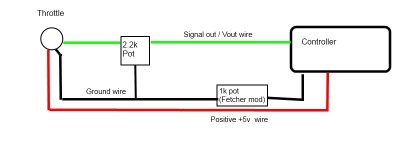
Back to your question I've made a quick drawing of the connections, I hope it's clear:

throttle_mod.jpg

The ground on the pot is the central leg.

The value of the 2.2k pot can be 1k or 500 ohm for a more fine adjustment imho.But I still have to try it on the bike.
 
puddleglum said:
d8veh said:
You can test with a 10K linear potentiometer. Join the red and black wires to the outer two pins and the signal wire to the middle one. When you turn it, motor speed will increase/decrease. Controllers normally want to see zero throttle before they give power, so you have to turn the potentiometer down first. You can sometimes get better response by putting a 1K resistor in series with the signal wire, but that's not necessary for testing.

You can use the pot as a speed control, and then use a separate switch on the red signal wire to activate it, so that you get motion when you press a button, and the speed depends on the potentiometer position.

Some stand-up scooter throttles work like a switch = on/off, so you might have the wrong type of throttle. Also, some work backwards, i.e. full power when shut and no power when open. You can only find the correct type by trial and error.

I'm a little confused by this, sorry. Forgive me but I'm pretty much an idiot when it come to electronics. I definitely have a variable speed throttle though. Are you suggesting to replace the existing throttle with a 10k pot. and a on/off switch, or put the pot in parallel with the throttle and use a switch to engage it, or something else entirely?
Ok, if you're sure that the throttle is definitely a variable one. It wasn't clear in your original post.

I use the potentiometer arrangement instead of a throttle on one of my bikes, and I in addition to a throttle as a cruise control on two others.
An ebike controller is looking for a variable signal of between about 1 and 4v to control speed. Most ebike throttles have hall sensors with a 5v supply, and the signal depends on position of magnets in the throttle relative to the sensor. Some ebike throttles have a potentiometer in them that works the same as I described, Electric stand-up scooters sometimes have an on/off hall sensor in them instead of a variable one, which gives full power or nothing. if you have one of those, no additional smoothing circuit will help.
 
spuzzete said:
Hi puddleglum,

I've seen your build, awesome work!

Back to your question I've made a quick drawing of the connections, I hope it's clear:


The ground on the pot is the central leg.

The value of the 2.2k pot can be 1k or 500 ohm for a more fine adjustment imho. But I still have to try it on the bike.

I'm hoping to try this out in the next few days. I picked up a couple of 1k pots and I think I'm going to test it on my spare motor/controller on the bench first. I know it is just my ignorance, but I'm still trying to understand how the speed control pot in the diagram is going to vary the speed when the fixed resistance is in series with the signal and the varying resistance is tapped to ground. I assume that it gives you full speed down to some reduced speed, but, would someone mind explaining how it works. Thanks.
 
Hi puddleglum,

I tried the mod and it works perfectly. I am no electronic technician but the potentiometer should act as a variable voltage divider in the schematic I uploaded. It basically stops the voltage increase after a certain level that you set rotating the pot.
I used it yesterday on a long ride to limit the top speed and increase the range, it was very effective and I completed my ride no problem.

8)
 
I tried a 1k potentiometer today with a knob.
I bought it from an electronic shop here in Calgary.

The wiring is different:

View attachment 2

The right pin is now connected to gnd.
Maybe the little ones I was using before have the swipe in the wrong pin? They were from china so who knows.

The result on the bike:

IMG_0535[1].JPG

IMG_0537[1].JPG

It works pretty well.

8)
 
Thanks for the update. This latest diagram makes more sense to me having the variable resistance in the signal line. How did you find it was different? Did you just try different configurations until it worked or did you find the swipe was in a different spot with an ohmmeter? I was going to try this today but didn't get the chance. Now I'm glad I didn't, thanks. So, how much speed change do you get with the 1k pot?
 
I tried wiring the 1k pot the same as the other one but it didn't work. Then I checked it with the ohmmeter and I found the current configuration.

I can regulate the speed from zero to maximum simply turning the pot. So I can set it to max when I want a short and fast ride, or I can choose the speed for a longer ride. If the pot is set to zero the bike won't start when I push the throttle.
 
spuzzete said:
Hi puddleglum,

I've seen your build, awesome work!

Back to your question I've made a quick drawing of the connections, I hope it's clear:


The ground on the pot is the central leg.

The value of the 2.2k pot can be 1k or 500 ohm for a more fine adjustment imho.But I still have to try it on the bike.

Just for the record this diagram is incorrect, if the wiper of the adjusting pot is connected to ground then this will with certain conditions short circuit the output of the throttle which can be bad news if using a resistive throttle or a hall throttle. The fixed value of the adjustment pot is what needs to be across the output to the grn and the wiper of the adjustment pot then becomes the new throttle signal that goes to the controller as in the second diagram by spuzzete. Not sure if it relevent in this appication but the start point of the throttle will also change when adjusting the adjustment pot.
 
I got the trim pot installed as Fetcher recommended and it seems to have smoothed out the throttle nicely. The speed limiter pot is ready to install, but I have no room for it in the control box so it will have to wait till I can do some reorganizing in there I guess.
 
I have found that wiring a resistor in to the signal wire can give a set speed reduction. In some countries this might be a way to make an illegal bike legal.

I have deatiled my experinces here:

http://dorkythorpy.blogspot.com/2018/07/reducing-speed-of-ebike.html

I found a 1.2ohm resistor gave a approx 50% speed cut, whilst 0.6ohms gave a small reduction in speed if any. So the resistance required for optimal speed control in my case was in a very narrow band. For me it is likley around 0.9ohms.
 
rollingreenhills said:
I have found that wiring a resistor in to the signal wire can give a set speed reduction. In some countries this might be a way to make an illegal bike legal.

I have deatiled my experinces here:

http://dorkythorpy.blogspot.com/2018/07/reducing-speed-of-ebike.html

I found a 1.2ohm resistor gave a approx 50% speed cut, whilst 0.6ohms gave a small reduction in speed if any. So the resistance required for optimal speed control in my case was in a very narrow band. For me it is likley around 0.9ohms.

Do you mean 1.2K ohms?

The input of the controller has a resistor to ground, so by placing a resistor in series with the signal wire, it forms a voltage divider. The resistance to ground inside the controller varies with model, so some testing will be required. One downside of this approach is the dead band at the low end of the throttle will be much greater (you will need to advance the throttle more before it starts going).
 
fechter said:
The input of the controller has a resistor to ground, so by placing a resistor in series with the signal wire, it forms a voltage divider. The resistance to ground inside the controller varies with model, so some testing will be required. One downside of this approach is the dead band at the low end of the throttle will be much greater (you will need to advance the throttle more before it starts going).


I've found that by putting the voltage divider in the supply line, it leaves the low end untouched. And still reduces the top end out put...making for effective top speed reduction.


MAHDzVK.jpg


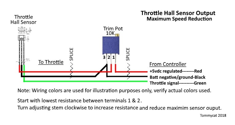
For this and other mods, as well as information on Hall Sensor Throttles... See this thread.
 
TommyCat said:
I've found that by putting the voltage divider in the supply line, it leaves the low end untouched. And still reduces the top end out put...making for effective top speed reduction.

Yes, that is a better way to do it.
 
What if you want the top end untouched, but want the low end to have a slower acceration/less torque off the line?
 
You really need some kind of ramp control. The CycleAnalyst has this function and would be one way to do it. The ramp control limits how fast the throttle signal can rise when you hit the throttle.

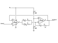
I've been working on a less expensive approach but my circuit is still in the design phase and I don't know all the component values yet. It's simple enough to build on a perf-board with wires. The op-amp circuit will limit the slew rate of the throttle signal with separate rates for upward vs. downward. The idea is you want the throttle to respond instantly when you let off, but slowly when you increase it. The resistors in series with the diodes will determine the rate in each direction. The upward rate resistor would be variable so you can dial it in.

Throttle Ramp1.jpg
 
@fetcher

Good for you if you can pull that off. I haven't built anything powerful enough that can't be controlled with a steady hand (yet) but I could see that being a thing for some people.

I have a question about your original mod that brings up the bottom end. I'm looking at the pros and cons of welding the clutch in a geared motor, and was wondering if it would be possible to dial in enough current "at idle" to overcome the drag of the planetary gears when coasting without having the bike creep ahead when you don't want it to. Justin at Grintech seems to be able to accomplish this with their GMAC motor using the phaserunner controller. But I'm poor and don't mind dicking around with a soldering iron and a potentiometer if I have to.

https://www.youtube.com/watch?v=cnaucA7qVGs

Around 4:15 or so.

Cheers.
 
Using a 10 turn pot you can get the motor to barely creep but it might not keep the clutch engaged when you are moving at speed. It would depend on the controller.
 
Back
Top