Direct-Drive conversion of the new GNG/cycmotor X1-pro 3000w

crossbreak

1 MW
Joined
Aug 2, 2011
Messages
2,884
Location
Germany
Hi,

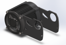
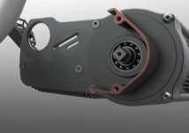
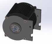
the X1 should be shipped out in mid December according to Jon from cycmotor. So far we know that the motor should run at around 9000 rpm loaded with a 20s battery (the motor is ~150KV, 20s is the max voltage the controller can take) and comes with a 1:6 planetary gear reduction.

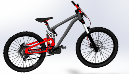
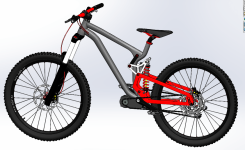
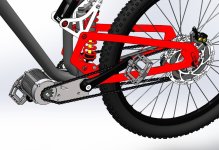
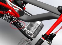
The total reduction for driving the cranks is 36:1, so the cranks spin at roughly 250rpm, which is a lot. Tells me that this drive is predestined as a (dual) chain drive direct to the wheel (dual since there is 1 chain for pedaling and 1 chain for the motor). I aim for about 60kph with 26" tires so i'll try a 3:1 reduction from planetary output to the wheel, a total of 18:1 from motor to the wheel.

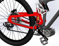
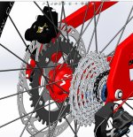
I want to use a left hand drive with a 36T MTB chainwheel (104mm BCD x4) on the wheel and a 12T sprocket on the planetary output, according to my calcs this chain drive should hold up well but still keeps a low profile, as the 36T chainwheel is smaller then the 203mm brake disc that is left to it. A protection disc between brake disc and chainwheel protects the disc from chain oil spray and a cover on the front sprocket will further mask the chain drive.

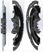
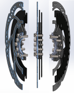
The chainwheel will be mounted to an adapter that is bolted to the brake disc flange of the wheel hub, a custom 104mm BCD brake disc is also mounted to the same adapter plate. I am going to laser cut the sprocket, disc and disc adapter from 1.4571 steel, so anyone who wants those custom parts is welcome to PM me - the more we cut, the cheaper it gets.

Attached a pic of an adapter that i have at hand, but there is more to come. Any comments, ideas or contributions are welcome!

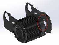
Edit: This is a modification to the X1 Pro Gear Type Drive with the shorter housing (opposed to the longer #219 chain type drive) . I bought it since it has the freewheel in the planetary drive freewheeling in the right direction. "Drum" argumented that this freewheel should be a sprag type clutch, which can be turned around without much hassle. So this mod might be done with his proposal with the chain drive model as well https://endless-sphere.com/forums/viewtopic.php?f=28&t=95704&start=75#p1426073
 

Attachments

  • 250825281_50525.jpg
    250825281_50525.jpg
    169.4 KB · Views: 9,684
250rpm at the pedals is a huge fail if that figure is at 72v because at 48v it is still well over 150rpm.
Huge dealbreaker for me. Might as well build something on a motorcycle chassis if you cannot add pedal power.

That being said, talk about a great situation for a direct rear drive. .20mm lam motor and easily mountable package.. It's a poor man's recumpence drive. :thumb:

I look forward to seeing what comes of this thread. Thank you for being a pioneer. :)
 
Good idea Crossbreak. But do you think the small motor as a left-side-DD will get you up a hill from standstill with that gearing?
I also think that a DD is better for high power (4000W+). That's why the upcoming LR LHD single stage kit is on my list.
The LR has more motor mass (I forgot about rotor width and diameter of the GNG and bigblock ...bigblock is 60mm wide I think) so the LR should deliver much more low end torque if geared accordingly.

Look at this video and see how drastically the GNG is getting slower as the hill gets steeper.

https://www.facebook.com/CYCMOTORLTD/videos/317343372435193/

I hope it runs better with the foc controller.
 
thx neptronix, yes, this drive is really a recumpetence for the stuff cyclone/GNG has sold before :D never bought from them besides of bottom brackets, freewheels and other small parts though (which is actually good stuff to work with)
Anyway, as "my" dual chain type has the pedal input seperated from the motor input, you are welcome to install - say- a 52T chainring and a 11T sprocket for pedaling at 50kph+ without loosing any torque from the motor (52T-11T is what i have laying around). You can even add a Hammerschmidt drive or an internal geared hub so you can pedal well at 80kph. I once build such a bike and it was actually fun to really pedal at this speed 8) even if it is nonsense as we all know (wind drag during pedaling...better lay flat!)

@dolph: I can understant that you want to compare this drive with no reduction (DD-hubs) and single stage and muliti gear (as it is sold originally) reduction drives. But this is and stays a two stage. So it will have the shortcomings and benefits of one. How it competes is all up to speculation yet, lets start this discussion when we have test data...this will be interesting though, i am with you at this point. Also the vid you talk about was with a 13 or 14s battery. This conversion aims on high reduction and thus high rpm. With a 13s battery and a converted drive, 45 kph is all you would get...so get a 20s battery or you are stuck to low speeds with this build

Below are some cheap mockups i made tonight

neptronix, do you remember the bike CAD model from somewhere :lol: ?? deja-vue? i am always amazaed what color can do...

There might be an obvious problem with chain/BB-interference that has to be adressed. The idler that tightens the chain is also still up to your imagination
 

Attachments

  • mockup2.png
    mockup2.png
    113.6 KB · Views: 9,617
  • mockup1.png
    mockup1.png
    134.4 KB · Views: 9,617
Man, i need to learn how to use that software. It would have saved me many headaches.

A taller gear in the front and back sounds like a good solution for preventing the chain from hitting the "crank shaft". Also, the second you sit on the bike, the rear shock compresses and pulls the swingarm up, giving you >10mm of extra clearance.

But you already knew that :)
 
we have got an even more hassle on the other side that i just noticed when adding the motor overhang on the right (pedal) side when turning around the motor output to the left side. A 52T chainring?? (pictured is a 36t if i remember right) I might be dreaming.. :cry: ..we definitely need longer mounting brackets. something in between the "gear" version and the "chain" version. this can be done with affordable effort thanks to lazering sheet metal. I'd really like to have aluminum here for stiffness and weight reasons though. Still, alumium can be lazered at only slightly lower cut quality than steel at this low thickness.

 
If this is a model of your frame, then you have a big limit here.

On another frame, you could mount it on the swingarm as close to the seat tube and take a very minimal hit on unsprung weight.
 
man, this is still the same stolen model that GNG/cycmotor stole from this great guy from https://grabcad.com/library/mtb-bike-redesign-by-pax-1

Edit: just fell over the fact that actually Joris Deschamps has made this great model of the bike in 2014 :eek:
https://grabcad.com/library/freeride-mtb-1

feel free to download and modify! Have fun!! solidworks isnt that hard to learn. PM me if you need advise.

my bike has a much "straighter" downtube though. The way the new GNG comes in stock, it might just fit on the left side for my bike...still it wont fit a 52T chainwheel on the pedal side, since i want to pedal at high speed
 
just some model of the drive, next step is to disassemble and reassemble it with the drive turned around. As i only had some measurements from their homepage to make this model, some dimensions might be off and will be corrected as soon as I've got the drive on my desk 8)
 

Attachments

  • model2.png
    model2.png
    90.4 KB · Views: 9,451
A large CS and rear sprocket would make for better clearance, chain life and possibly keep lube off the disk as well.

I've been mulling something similar but keeping the motor sprocket on the right then using a fixie IGH as a 3spd jackshaft which would output on the left. Possibly with a belt as primary drive.
 
Although 250 rpm at the crank at 72 volt operation , or even 150 rpm at the crank when run on 48 volt is too much for human legs ...
by running a left drive you can just not peddle when using the upper power levels. This is achieved because when not peddling you are using the freewheel on the right side / rear cassette freewheel.

Just like you do when coasting down hill not peddling .

Crossbreak , I would be interested in knowing what power levels will run the cranks at about 70 rpm , as that is a real comfortable cadence anything faster and the cardiovascular system is working too hard for us older riders.
 
Are you saying you are going to make your own side plates to move the motor further away from the BB/Front Chainring ?

If so then side plates that will be angled so as to be used on the many/most of the full suspension frames these days, frames that have a
" dog leg " angle as the downtube comes close to the Bottom Bracket.

In other words ... dog leg angled side plates .


crossbreak said:
we have got an even more hassle on the other side that i just noticed when adding the motor overhang on the right (pedal) side when turning around the motor output to the left side. A 52T chainring?? (pictured is a 36t if i remember right) I might be dreaming.. :cry: ..we definitely need longer mounting brackets. something in between the "gear" version and the "chain" version. this can be done with affordable effort thanks to lazering sheet metal. I'd really like to have aluminum here for stiffness and weight reasons though. Still, alumium can be lazered at only slightly lower cut quality than steel at this low thickness.
 
ScooterMan101 said:
Are you saying you are going to make your own side plates [...]
If so then side plates that will be angled [...]

yeah sure we could do this, but this is just a design matter, let's make it actually work in the first iteration


tried to just flip sides ind CAD, but unfortunately, the bearing flange of the right side seems to be integratet into the sideplate. So just flipping this sideplate doesnt work :cry: At least it looks like it's integrated into that plate in the video

I think i'm gonna cut the original sideplates and mount new ones to whats left over from the old ones. At least the front controller bolt hole can be recycled :) the last pic shows what i'm gonna start with, that pic is already flipped around - all stock besides the 2 cuts. The controller will be mountet in the same space as before between the new sideplates
 

Attachments

  • drive side.jpg
    drive side.jpg
    18.7 KB · Views: 9,324
  • bearing_flange.png
    bearing_flange.png
    57 KB · Views: 9,324
  • cut.jpg
    cut.jpg
    23.2 KB · Views: 9,312
ScooterMan101 said:
[...]
by running a left drive you can just not peddle when using the upper power levels. This is achieved because when not peddling you are using the freewheel on the right side / rear cassette freewheel.
[...]

sorry mate, but i dont get what you want to tell. I cannot peddle, cause when i dont pedal, i use the freewheel? I mean, there is obviously some truth in the second part of the second sentance.

Get a SRAM Dual Drive hub and put a 44t chainring front, 11t in the back. As the hub as a reduction of 1.36, you will end up with a gear ratio of 5.44, enough to pedal well at 60kph at a cadence of 90rpm and 26" wheels.

The left hand drive completely does its own thing, no matter if you pedal or not. Get a torque sensing BB and connect it to the throttle input of the controller. You get a nice human (or superhuman) feel, even if pedaling at high speed (mph/kph) with low pedal rpm and real added human power (low compared to the motor though). Did something similar with a DD hub, it felt great (besides the the 10kg/20lbs anchor in the rear axle). Not sure yet if ill go for a hammerschmidt again or the cheap but weak SRAM DD3 hub. Hammerschmidt+Torque sensing BB wont be easy to get them to marry i guess
 
extended those sheets by 40mm, clearance and looks are much better now. Lengths is something in between the gear and the chain version

The issue that the right sheets eats into the pedal chainring bothers me though. The controller is 83mm wide, asking myself where to steel this space without messing up the (both) chainlines, or at least not the pedal side. Guess this will be hardest nut to crack...
 

Attachments

  • sideplates.jpg
    sideplates.jpg
    116 KB · Views: 9,277
  • sideplates2.jpg
    sideplates2.jpg
    127 KB · Views: 9,277
  • sideplates3.jpg
    sideplates3.jpg
    115.6 KB · Views: 9,272
Crossbreak,

Have you seen this ? ... https://www.youtube.com/watch?v=wh1Nu2IwFHw&feature=youtu.be

From this thread ... https://endless-sphere.com/forums/viewtopic.php?f=28&t=82929&start=25

Middle of page 2 and down .
 
crossbreak said:
The controller is 83mm wide, asking myself where to steal this space without messing up the (both) chainlines
maybe it's possible to guide the way back of the motor chain (the return way on the left side, the lower side) so it goes around the controller that then overhangs the left sideplate through a window. Sorry for no CAD pic, i'll add that ASAP
 
cool, ETA for the bare motor is early February, then i can design and cut the parts. I will add the chain tensioner and controller window then as well.

I think i will also try a version that has the motor mounted on the swing arm, for bikes with longer wheelbase this is a better design IMO, since then there is more space for the battery. Anyone who wants to try this?

Any wishes for the kit? Different chain or gear ratio or do you have some other ideas?
 
Will your design work with bikes that have rear widths of ...

10 mm x 135 mm wide drop outs ?

12 mm x 142 mm wide through axle design rear swingarm ?

12 mm x 148 mm wide through axle design rear swingarm ?

What rear brake are you designing this with ? , since it needs to be as small as possible .
Shamino XT perhaps with ice tec pads ? dual piston calipers look like they would be too big ?

Would love to see a rear swing arm mounted motor, ( Lighting Rods, Mike has done this with one of his motors on a FUTR and looks like a great design , except for the high price of the frame )
Any possibility of you are someone you know designing a frame like the Beta or Storm , with 68-73 mm wide Bottom Bracket Shell, and motorcycle style swing arm , and way to put the batteries in the side , with weight less than the Vector Storm frame ?

A new bike frame designed with the motor on the swing arm and longer wheel base is much needed now for DIY E-Bike Builds.
 
@ Grantmac

What diameter of brake disk?
203mm, same dimensions as a magura Storm HC 203 disc, but with 4-bolt 104mm BCD, not the normal 44mm BCD 6-hole pattern. The adapter itself mounts on this 44mm BCD 6hole hub interface to the hub

Also does the caliper mount at the same offset?
Yes. I can send you a cut view/upload it in the thread so everyone can see it.

Approximate price?
Around 100€ for the adapter parts incl. brake disc, i will have a look what is the exact amount tomorrow or on sunday.
I have no price for the sideplate yet since the design is not finished yet. Hopefully the motor arrives in the next 2 or 3 weeks.

@Scooterman
the kit should fit all 3 mentioned axle standards. Depending on the swing arm design, it could be necessary to adjust the left chain line. This is something we can only really do in real world testing, hard to do it in CAD since mountain bike frames are so different.

the brakes that i want to use are the Magura MT5e, they arent expensive, bite very well and come with a nice, waterproof HIGO connector. I did not design them in CAD, but the dimensions are about equal compared to those in the model.

I stick to local suppliers where i can and those MT5e are produced nearby.
Shimano has no real ebike brakes, no? Never seen some..do you have a link? Those icetec brake disc have poor steel quality compared to Magura, I once had a pair of them and i was not convinced by them.
2-piston brakes wont fit with the 36T chainwheel on the rearwheel adapter, 4 pistons are needed. With a 32T also 2 piston brakes would fit, for example the cheap shimano BR-M395

The swing arm mounted motor would be very nice, but i think that is a project for 2020, we need to find someone that is experienced in frame building, it shall be made from 7020 alloy or something equal to keep the weight low and the stiffness high. The battery shall be fit where the the downtube is normally to keep the center of gravity as low and as far to the front as possible. I have started the design already but dont have pictures yet.
 
I mention the Shimano XT brakes only as an example of the size of a brake caliper to see if they would work with your custom made Rotor/Cog adapter plate , and because for the price of them , often sold for $ 80 each through internet bike part vendors like CRC / Jensonusa , etc .
Shimano 300 series brakes are very cheep here in the U.S. and through CRC .

I have not yet used Ice Tec Disc Rotors, Just the Regular Shimano Disc Rotors, so it is good to hear a comparison to regular discs . Do the Magura Rotors work better than Regular Shimano Rotors ? I have several Shimano Standard Rotors left , some still in boxes so I will be using Shimano's.

If you are designing your Disc Rotor/Cog around the Magura Caliper this is a very important thing to know in advance for anyone wanting to buy your left hand drive conversion of the X1 Pro motor so they do not buy other brands of Brake sets.

For those of who already have brakes it would be good do know what dimensions of caliper would work with your rotor/cog set up, to see if our existing brakes would work or not.
There are aftermarket electrical cut off switches that can be installed on existing brake handles .

However ... with a quick Google search for Magura MT5e 's I found a place , Starbike.com that sells the E-Bike Switch Magura MT5e 's for $ 95.87 each, so I can now see , at least at that price or lower , it would just be better to get the Magura's with the already installed cut off switch .
Which one to buy, with Opener Switch or Closer Switch ?

Since you live so close to them ( Magura ) It would be great if you could get a good enough price from them to pass that along to us here on E.S. , that would buy from you.


Am I reading right that your adapter for Disc Rotor and Rear Cog will fit on any Stock Wheel ?
 
here is the section view of the disc rotor and rear left hand chainwheel assembly. Plus a second one that is rotated by 90° to the first one

there you can see how the assembly is done so that the disc rotor stays exactly in it's originial location, the blue plane is the one that is boltet to the 6-bolt hub disc flange
 

Attachments

  • disc_rotor_cheainwheel_cut_view.png
    disc_rotor_cheainwheel_cut_view.png
    85.9 KB · Views: 8,433
  • cut_view_2.png
    cut_view_2.png
    72.5 KB · Views: 8,431
Back
Top