The best first place to go to find out the wiring for that specific kit is the vendor that sold it. if they dont' have one either on the page you bought it from or that they can email you, some generic directions are below:
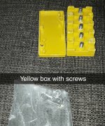
The yellow box is to put the three large phase wires from the motor and controller (yellow, blue, green) and the two large battery wires from the battery and the controller (red, black) into and secure with the nuts in the bag.
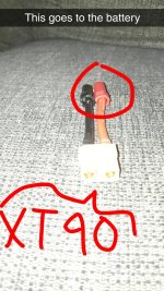
Red goes to red, black goes to black. Since your battery apparently has either XT90s or RC bullets (that's what is on either end of that adapter you show, but you don't show the actual battery's connector), you'll either have to change the ring terminals on teh controller to match those on the battery or adapter, or you'll have to change the connectors on the battery or adapter to the ring terminals.
The other colors might match, they might not; you'll have to determine that experimentally. There are a number of threads about that but the easiest is titled How to determine the wiring for a brushless motor, and has a matching entry in the ES wiki (linked in the threads about that at the top of each forum).
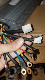
The two sets of 5 wires from the motor are two independent sets of hall sensors. You only need one of them, the other is a spare in case the first fails. There may be a 5-pin connector or bundle of 5 wires on the controller that go to these. Usually black goes to black, and red to red. The other three wires may also match color to color, they might not, you'll have to determine that experimentally just like the larger phase wires above.
The rest of the wires on the controller you'll also have to determine experimentally if there's no markings or diagram, if they dont' have matching connectors to plug into throttle, brakes, PAS, etc, that all came with the controller. (even if they come with it there's no guarantee that plugs and wires will match in type or color; some "kits" are not actually kits, just bundles of parts thrown together into a box that can probably be made to work together eventually, with enough DIY on the buyer's part).