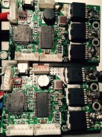
Damage of VESC's connected by can bus

erwincoumans

100 W
Joined
Apr 2, 2015
Messages
141
It is possible to damage a VESC when connecting to another VESC over can bus
(to share single servo PPM signal). This happened to me already with 4 VESC's,
soldered by 2 different people. Once damaged, some part of the VESC becomes really hot,
as if the voltage regulator doesn't work anymore. You will have to trouble-shoot and replace parts to make the VESC work again.

Only two wires of the can bus are connected: CAN Hi and Low, on Vedder's advice.

It is not clear why this happens. I just wanted to share this info, in case anyone else experiences the same.

By the way: when using a single servo PPM signal, connected to two VESCs to the servo pins, I have never experienced any problems so far (one VESC connects the 3 servo pins, the other VESC connects only ground and logic pin).
 
Wow ...
I'll have to be careful.
I plan a dual diagonal with VESC.

Thanks for the warning !
 
Thanks for sharing your experience here.

So, to clarify (and show my noob'ness), using a 3 wire servo "Y" from the receiver to dual ESC's is fine (minus one power wire on one)? BUT then you'd lose some features like traction control correct?
 
That is very strange. I have been running a dual diagonal setup with 12s and can-bus for months now without any problems. Connecting them using the servo connectors when using the same battery pack is _not_ a good idea and will most likely give you problems soon.

Can you post the exact details of your setup?
 
Vedder - can you also show us your setup that works OK as well? I'll do what you do as a starting point...

Batteries ---->Y ======VESC's
Receiver ----->VESC 1 --can bus--->VESC 2 ======Motors

Maybe something a bit easier to understand, but what's the optimal/correct way to run dual motors and keep traction control?
 
I am running dual vesc using canbus no problem. Only need connect two wires. The two middle pins (2 out of 4)

I also ran dual vesc using servo splitter no problem.

Traction control only works with canbus.
 
vedder said:
That is very strange. I have been running a dual diagonal setup with 12s and can-bus for months now without any problems. Connecting them using the servo connectors when using the same battery pack is _not_ a good idea and will most likely give you problems soon.

Can you post the exact details of your setup?

Dual hub motor wheels (by Pediglide), each brushless motor is connected to its own VESC. Each VESC has its own battery, like 6s, 22.2V, 50C to first VESC and 7s battery from Yuneec E-go to second VESC. So I am not using a shared battery pack.
Then, Arduino has 3 servo wires (ground, 5V, signal) to one VESC and 2 wires (ground, signal) to second VESC.
Works perfect, for over a month.

Now, using can bus, same setup, except the 2 wires servo signal removed, because signal is shared over can bus.

The can bus setup works for a while (several days), but all of a sudden, one VESC gives up. This happened several times. I am asking some colleagues to troubleshoot this. Note that one VESC was build by silviasol, this one worked for several weeks, until using can bus. Same happened to the VESCs we build. We can build about 15 VESCs, so I have some more testing capacity. Once your VESCs arrrive here, I'll try them too, perhaps it is a build-issue after all.

Do you need more details?

If you are interested, I can mail one of the affected VESCs to you.
 
Hmmm... I may be *way* off base here, but...

One motor is being powered by 6s
One motor is being powered by 7s

Correct?

25.2v x your motor kv (say "standard" 270kv 5060) = 6804 motor rpms
29.4 x 270kv 5060 (likely not what you have but still relevant) = 7938 motor rpms

What am i missing? This seems like it would make the "traction control" feature over can bus work like crazy for the 1000rpm difference in motors!

Not sure what your Arduino is doing in this setup, so perhaps this is accounted for?

I'm a noob, but it *seems* like it would be similar to running your 4x4 vehicle with different ratio differentials (no bueno)! Wheels moving at different speeds etc.

If i'm waaay off base and this is figured for... just seemed like it might be significant.

HTH - GL!
 
chuttney1 said:
Something tells me there may be an electrical shortage happening.
Unlikely but possible indeed.
The VESCs, batteries and Arduino are solidly attached by screws in a closed plastic box, and all cables are insulated.
sl33py said:
Hmmm... I may be *way* off base here, but...
One motor is being powered by 6s
One motor is being powered by 7s

Correct?
Yes.

Both wheels touch the ground and have roughly the same RPM. Both are using current control,
so one wheel 'pushes' a bit harder than the order. You only need traction control if wheels have largely different RPMs,
which is not the case. Even if so, why would traction control cause damage, it is just 'logic' applied to current control, right?

Not sure what your Arduino is doing in this setup, so perhaps this is accounted for?
The Arduino takes care of creating a single servo signal from the bluetooth remote input. There is nothing accounted for.

Note that in the case of two VESCs with can-bus, the two VESCs don't share any common ground, because of separate batteries,
and only connecting the CAN Hi/Low wires (the 2 in the middle). If not using CAN bus, the servo signal is split, and there is a common ground over the servo wire.

Do I need to add a common ground when using CAN bus when using 2 separate batteries?
(connect the ground of both batteries for example?)
 
I'm not sure if it's that simple. In a mechanical system like a 4x4 w/ FR and RR diffs - you do not mix ratios or you blow up gears.

Brushless obviously is not as constrained, but i wonder if you kept everything the same, except supplied both with identical voltage (both 6s or both 7s) - same issue/problem w/ failing ESC's?

Do you have another 6s or 7s pack to test this? Do you have a repaired/good VESC(s) to test this?

So this is a Push/Pull setup w/ one motor on each truck? Or both same truck (rear or front)? And your Arduino is a Wiimote or similar TX/RX setup?

HTH - GL!!
 
sl33py said:
I'm not sure if it's that simple. In a mechanical system like a 4x4 w/ FR and RR diffs - you do not mix ratios or you blow up gears.
There are no gears, nor pulleys, nor timing belts, these are a dual hub motor on one truck. In other words those motors are completely independent direct drive motors.

I'll test with some new VESCs soon, using two 6s and a shared ground between those batteries.

Arduino uses a Playstation Move bluetooth remote, which should be similar to Wiimote.
 
long day and a bit brain-dead (need more coffee). Sorry Erwin - i saw above this was a hub motor!

I still think a suspect problem is two different voltages and each motor having different RPM's. I'd be willing to bet a shiny nickel (big money) that standardizing voltage will eliminate your problem. Two different RPM's on two motors traversing the same ground has to be more work for the motors and ESC's. Either load on one motor or the traction control working harder to even the rotations.

GL!
 
I am no nuclear engineer but again common sense would dictate that for electrical setup you should unify everything as far as current level go.

To me trying to work out 2 ESC plug together to get a single signal but one is xV and the other is yV is bound to fail at some point. Your problem comes surely from that. Sl33py example about ratios was correct but misapplied ; you don't mix ratios on a 4x4 truck because you blow gears from unmatched stress.

Even with indépendant hub motors, unless there are two totally distinct systems with no plugs whatsoever, you mismatch the electric strain on both ESC. bound to fail. BTW why the voltage difference ?
Post edited, sorry for auto correct
 
Regarding shared servo signal:
If you have separate battery packs, you can share the same servo cable. The problem comes when you have a shared battery and also connect the logic ground.

The CAN-bus should not have problems with the different batteries (and different voltages). Current control should be more or less unaffected by that. One thing that could happen is that you reach full speed and the 6s side cannot go any faster and the 7s one starts pushing it. Tracking the motor when that happens could be difficult since the body diodes in the FETs will be conducting, but I'm not sure if that is the problem either.

There were some problems with the CAN-bus code that I solved a few days ago, so maybe it works better if you use the latest firmware. I have been using CAN-bus with the nunchuk a lot without issues, but the PPM implementation is quite untested.

If you are interested, I can mail one of the affected VESCs to you.
Have you figured out which component failed? What is the voltage on the 3.3V rail? If you can figure out what failed it will give me some idea, but if you can't repair the ESC yourself sending it to me will help. I'm sure I can repair it and figure out what failed.
 
vedder said:
Have you figured out which component failed? What is the voltage on the 3.3V rail? If you can figure out what failed it will give me some idea, but if you can't repair the ESC yourself sending it to me will help. I'm sure I can repair it and figure out what failed.
Yes, the can bus transceiver was the part that got hot and failed. Once it was replaced, the VESC(s) started working again.
The voltage on the 3.3 rail was 1.6V on one VESC (getting hot transceiver) and 3.3V on the other VESC (getting hot transceiver).
So my problem is solved for now, but it is not clear why they started failing.

I will try the new VESC firmware and report if it happens again.

Would connecting the ground between the two different batteries (6S, 7S) help at all, or would that not make any sense?

One of the things I tried is going forward on both wheels, full throttle (using PPM current control) and then suddenly
go reverse, full throttle, while the board was hanging at the ceiling for testing. Could the abrupt change in velocities cause a CAN bus issue?

Thanks for the help,
Erwin
 
erwincoumans said:
chuttney1 said:
Something tells me there may be an electrical shortage happening.
Unlikely but possible indeed.

I should have been more clear what I first meant. I was actually referring to your VESC controller. Reading all comments made, its a learning experience.
 
chuttney1 said:
I should have been more clear what I first meant. I was actually referring to your VESC controller. Reading all comments made, its a learning experience.

Ah, ok. Luckily it was just the CAN transceiver that got burned this time. On one occasion I swapped the power leads by accident, and the motor controller (DRV8302) smoked. My colleague replaced it and all worked again. We have soldered about 6 VESCs now, all by hand (no reflow) which helps trouble-shooting: by experimenting, messing things up and trouble-shooting using the schematics, I'm getting better understanding of the controller. In case anyone else has a similar issue in the future, attached is a picture of the VESCs with an oval around the CAN transceiver that we had to replace.

VESC_CAN_Transceiver.jpg

I really like the concept of full open source hardware and software, so I'm glad Benjamin shared all and documented the VESC pretty well.
 
erwincoumans said:
Yes, the can bus transceiver was the part that got hot and failed. Once it was replaced, the VESC(s) started working again.
The voltage on the 3.3 rail was 1.6V on one VESC (getting hot transceiver) and 3.3V on the other VESC (getting hot transceiver).
So my problem is solved for now, but it is not clear why they started failing.

I will try the new VESC firmware and report if it happens again.

Would connecting the ground between the two different batteries (6S, 7S) help at all, or would that not make any sense?

One of the things I tried is going forward on both wheels, full throttle (using PPM current control) and then suddenly
go reverse, full throttle, while the board was hanging at the ceiling for testing. Could the abrupt change in velocities cause a CAN bus issue?

Thanks for the help,
Erwin

Avoid connecting the logic ground if possible. If the CAN transceiver failed, the problem can be that the termination resistor R401 has too low value (I don't know why I decided to use 100 ohms by default). Try replacing it with 220ohms. The only difference on my setup is that I have higher value for R401. I have not killed any CAN transceiver at all so far.
 
vedder said:
Avoid connecting the logic ground if possible.
I was planning to connect the battery grounds, close to the batteries (before the capacitors), is that OK?
(not the connecting the logic ground of the CAN BUS)?
vedder said:
Try replacing it with 220ohms.
OK, I'll try that. Thanks for the help.
 
erwincoumans said:
I was planning to connect the battery grounds, close to the batteries (before the capacitors), is that OK?
(not the connecting the logic ground of the CAN BUS)?

If you run CAN-bus it shouldn't matter too much, but not connecting the grounds at all is better if it is convenient. If you use a split servo cable, you should connect the logic ground and not the battery grounds (the only way sharing a servo cable is ok is if you have separate batteries).

Is there a reason why you want to connect the battery grounds?
 
I've got a similar problem with one of my VESCs. Was working fine until I connected them together over CAN bus. 100% certain that I got the wiring right and no electrical shorts. No idea why it would have failed.

Testing the resistance between CANH and CANL its reading 4ohms - should be 100.

Replaced resistor R401 with a new 100ohm. Still reading 4ohms across CANH and CANL. think the CAN transceiver chip must be blown ?

Also the voltage regulator gets really hot when I connect the battery
 
Stielz said:
I think the CAN transceiver chip must be blown ?

Also the voltage regulator gets really hot when I connect the battery

Yes, it sounds like the same problem. The Mouser part number of the CAN bus tranceiver is on the BOM :)
Oh, and replace the 100ohm by 220 ohm, according to Benjamin Vedder.
 
Back
Top