mosfet testing

whatever

100 kW
Joined
Jun 3, 2010
Messages
1,297
some results testing resistances of irf4310 mexico plant fets
took fets out of a controller which failed ( due to solder melting on the buzz bars and shorting out high amp section)
anyone want to hazard a guess at which fets are the goods ones? fets no.1to5 or fets no.6to 12??
4310 testing.JPG
 
just did a test using diode setting on multimeter to see which fets are turning on/off.
It confirms that mosfets 6 to 12 are the good mosfets.
So I guess you can say to do a quick test on a fet you can use resistance, the only resistance reading you should get is across the drain and source legs, where the negative meter probe is on the central leg ( drain) and the red probe wire on the source ( right leg). Probably wouldn't hurt to just touch fingers across the gate and source legs to turn off the fet before doing the resistance test.
maybe useful to someone
 
thanks for the link, there is a very cool test procedure I got shown a long time ago, I'll see if I can remember how to wire it up.
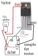
It was very simple test, you use a 12v ( or similar) and light globe, and by touching one finger on the fet ( I think the gate ) and another finger on the pos/neg battery terminals, you can make the globe go on and off, its a very neat little test, I drew the simple circuit up years ago and tried it, if I could find the picture i would post it, but i'll have to wire up the circuit to remember it. Its a very neat little test, will post pics etc when i get it done. The fets being so sensitive a tiny current goes via your body enough to turn fet on and off. Simple and quick when wired up.
 
ya rick, got it some time back, tried to post reply but wouldnt let me in that thread, very very useful info.
 
question ricky boy:
fet turned off; you have negative meter probe on centre leg ( or backing plate), positive on the source ( right leg), put meter on resistance reading, I get values in the kohmn region. What exactly is this resistance reading measuring? On a good fet its the only resistance reading you can get from a fet as far as I know.
would it be measuring the leakage between source and drain when fet is off? or something else?
 
whatever said:
question ricky boy:
fet turned off; you have negative meter probe on centre leg ( or backing plate), positive on the source ( right leg), put meter on resistance reading, I get values in the kohmn region. What exactly is this resistance reading measuring? On a good fet its the only resistance reading you can get from a fet as far as I know.
would it be measuring the leakage between source and drain when fet is off? or something else?

with the meter BLACK (-) on the Drain and the RED (+) on the source, you should be measuring the forward conduction of the built in protection diode. in the ohm meter ranges the meter supplies a calibrated test voltage and current to the device being tested. the meter then displays the voltage drop across the device under test. the problem is that on the Kohm and MegOhm ranges your meter may not supply a sufficiently high voltage to overcome the forward voltage drop of this diode. in the upper ranges this voltage is often less than 300mV and only a few mA. you can check this on your own meter. just switch to one of the ohms ranges and use a second meter to read the voltage.

that is why the diode range should be used on the meter. the diode range usually supplies a testing voltage over 2.5V. this is high enough to overcome the voltage lost in the diode. on most meters the 200R range will also use a test voltage of over 2.5V. the meters testing voltage and current is reduced in the higher ranges to only a few milliVolts and only a few milliAmps. the forward conduction of the diode depends on the current flowing through it . at very low currents the drop is lower. at the very low currents supplied by the meter you will show some forward conduction. the meter will display this as a very high resistance.

rick
 
great info thankyou I will do some more fiddling with my meter, just what I needed.
just been testing fets using a very very simple set up as per below pic, works a treat.
Can just touch gate then positive battery with fingers to turn on fet, touch negative battery to turn it off.
Could expand on this simple technique eg. use a string of leds to show if switching fully on ( pretty easy to judge by lightglobe brightness though). Could also make up a simple test unit based on this to verify which phase of fets has blown in a controller.
thanks to warwick smith of numurkah secondary school who showed me this simple test method about 10years ago.
another use for this very simple circuit could be a touch switch on/off for low voltage house lighting.
I will add some more pics of this simple test circuit as I have it setup on kitchen table, but will make a new thread for it
as I think its very easy for anyone to build this circuit within about 10mins.
Just need car taillight or blinker globe, sla battery and two alligator clips.........simple as
it also demonstrates how sensitive these devices are, in that the tiny current that flows via your hand ( or body) is enough to turn them on/off.
fettester1.jpg
 
For that circuit I would add at least a 10 to 100 ohm resistor in series with the gate, to help protect against the destructive currents ESD from your hand could cause, if you have a charge built up. ;)
 
would have to be pretty unlucky to have a static build up while sitting testing fets, give it a try its a nifty test.
 
Oh, I've used that method among others; I just prefer to be safe rather than sorry when dealing with ESD, since just by moving your arm in your sleeve a tiny bit, or taking a step across the floor, moving your toes within the shoe, even just breathing if in dry enough air, you generate a charge. The charge might not be enough to hurt anything, but you'd never feel it even if it was. The device will, though. :p

I've seen (from pics with an electron microscope in failure analysis) what it does even just to a diode like the 1N914, even in an otherwise static-controlled environment where someone just didn't like wearing their static straps. :( (kept having all sorts of wierd display failures; the diodes would either open up or short out, for no good reason, but only on those displays made during one shift....)

And worse stuff on more complex semiconductors; problems that don't show themselves as total failures, but just increased or decreased turn on times, slightly different resistances, current flows, etc. Sometimes eventually failing, months or years later, when they probably would not have if not exposed to ESD. It's tough to know if the failure was ESD related without examining the silicon under high enough magification to see the pitting, splatter, and other damage often caused by ESD along the bonding wires.
 
Back
Top