XC836 "706ax3" 6fet controller wiring/pinout??? firmware?

BimmerTas

100 µW
Joined
Jun 10, 2016
Messages
8
Hi there.

Been struggling to find a wiring diagram/pinout for a controller i happened to pick up.

from a 'longwise' scooter 36v 12a... is all i can find about it... Thought i might be able to figure it out as there's only 5 pins! apart from the battery/motor. Doing my head in now though...

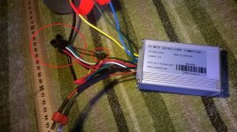
On the 5 pin connector all i have is battery + and - on red and black wires.... nothing on the other three... white, green, brown (with another 2 pin connector in series) ???

any ideas appreciated. Or if anyone knows of another model that uses same i might be able to find diagram for?
 

Attachments

  • controller111.jpg
    controller111.jpg
    210.9 KB · Views: 2,662
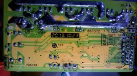
  • boardbottom.jpg
    boardbottom.jpg
    199.4 KB · Views: 2,663
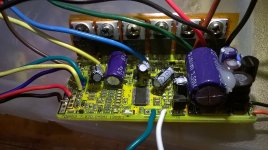
  • boardtop.jpg
    boardtop.jpg
    193.9 KB · Views: 2,661
https://endless-sphere.com/forums/viewtopic.php?f=35&t=81133&p=1194259#p1194259

OP probably in the wrong place... I can't find any information whatsoever on these

or anything that runs this particular MCU...

Any information would be greatly appreciated... or just a "there's nothing out there" "stop wasting your time looking for information that is not available" ;)
 
Thanks for moving the thread and the tips for searching, amberwolf. I'll have another go this evening.


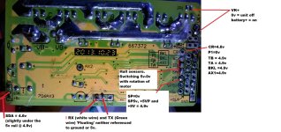
Also, what might help others help you figure it out is to power it on and measure all the voltages you get at each wire that comes out of the case, and list them here, along with what pad name (if any) that wire goes to on the board inside.

You could also list the pad names themselves, including ones that have no wires to them but do have labels.

voltages.jpg

VK+ (brown wire) - 0v, unit powed off -battery +, unit powered on. 5v rail active

AX2 + AX1 (nc) = 5v

CR (nc) = 5v

BKL (nc) = 5v

SP (nc) = 0v

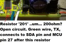
!!! TX + RX (green and white) = Open circuit (not 0v or 5v... um.... floating? no reference?) ... Have found culprit for green wire i think....
boardtopDed201.jpg

SDA = 4.8v

TA+TB = 5v
 
So... I repaired the 2 blown resistors (fuses in this case :p)

RX and Tx are now pulled up to 5v rail... my hall sensor throttle can't pull them down though... it reads 0.8-3.8 ish when just 5v and gnd are connected and signal is open circuit.
but
when connected to TX (green coming out of controller) it gets pulled high and twisting throttle has no effect.

Tried a trimpot too... which works to control 0.5-4.6v signal on RX (white wire)

Green stays over 4.5v with 250ohm between it and ground (50k trim and 200 in series limiting)

Me thinks whatever caused those resistors to blow has fried the chip, at least on pin 27 connected to TX/green wire.
(acting like its shorted to 5V (<250ohm) when circuit is turned on... behaves normally circuit powered off though, open circuit except for reverse protection diodes, same as pin 25(RX/white wire) which appears to work when circuit powered up)?????

Oh well... that's about as much as i'm prepared to confuse myself over a cheapy controller that may have been completely toasted by previous owner with no hope of recovery

EDIT : officially placed in my 'too hard' basket.... for now ;)
Better plan what to order when i can afford a battery to go with it ;)

In the meantime... I might keep reading up about MCU's etc. I have an arduino lying around here and it appears that all the main power circuitry is still intact on this one... maybe i can figure something out
 
I have a controller with the 706AX3 circuit board. It belongs to a Dillenger (Australian) Comfort EBike. To the best of my knowledge it is a chinese controller modified by Dillenger as they list it as OEM in their literature. I have not tried to contact them.

I am trying to replace a capacitor on mine [ another story]

I have had no success finding the identical controller. The wire colors on mine do not match yours. I will be glad to sent you my pinouts if you are still looking. The board seems to be built with identical components except some of the wires are different. Mine is not set up for lcd, it has pedal assist and throttle, 2 identical brake lines, similar red black battery wiring, hall sensor and phase wires. My camera is not working right now to send pics. I have the controller stripped down and am waiting for the capacitor. I may be destroying it handling it to try to figure it out. Had college physics a long time ago.

Your phase wire sequence [ l to r ] is yellow blue green
MY phase wire sequence [ l to r ] is blue/ A green/ B yellow/ C [The ABC corresponds to the letter on the board back/ noncomponent side at the phase wires]

My hall sensor wires are red [space] black
yellow / sc green / sb dark blue / sa [ the sc sb sa refers to letters on the board edge away from the big capacitor.

It looks to me like your phase wires are the green yellow blue red black on the side of the board away from the big capacitor.

If this helps at all I will try to get camera going or describe more
 
MCU XC836.... in bldc controller in E-micro-scooter "KUGOO S2", S3.....

Display alternative FW, two versions, one for atmega328p....: https://electrotransport.ru/ussr/index.php?topic=55186.0

Protocol (https://electrotransport.ru/ussr/index.php?topic=55186.msg1398542#msg1398542), maybe accepted ? ;).
 
Back
Top