Kx100 x QS3000 V3 x Fardriver ND96350 x LiPo28s 20Ahr

DingusMcGee

100 kW
Joined
Feb 23, 2015
Messages
1,004
Location
Laramie, WY
The conversion is done.

The Quandary was:
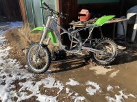
4D58FA98-7227-41BD-AF84-B003EC206634.jpeg

The motorless motorcycle weights more than my QS3000 edirtbike build?? What will I get????
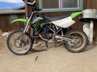

1D5A945F-A525-43B9-9F8F-25FE562609F0.jpeg


Motor choice?

D6A23699-D45B-41CA-B199-3C6109275EC4.jpeg

A QS1000, a QS3000 V3 and a QS4000 V3. The QS 4000 motor with sprockets aligned sat with right side 1” over right foot peg —- on a dirtbike? The QS3000 right motor face came to the inner foot peg edge so it was used.

Likely not much less performance going with the QS3000 instead of QS4000 unless I would install a 40,000 watt controller. With a 30000 watt controller performance would be similar but maybe a slight edge with the QS 4000?
 
Last edited:
Major problem:

The foot brake on the right side had motor in the way. I am not thrilled with a clunky small pad foot brake.

Solution:

Hydraulic rear handbrake handle on left side

55CB6B52-F2F1-4242-8694-3C4339C59AFA.jpeg
The 72” banjo ended brake line was found on eBay for $17. It is not DOT rated.

F83ADF1E-85EB-4713-9D8E-F3A3BF306DCC.jpeg
Arriving late was the 3 piece Dorman DOT rated hose. $58 delivered.
 
Last edited:
Cool, do you have pictures with the 138 90h (4kw) in place?
Close pictures on the other side with both 70 and 90h would be interesting.
Is your 90h the milled version? (I think there is a cast one now?)
What is the weight difference on them?
It looks like your front sprocket sits way too high in the picture
 
jbjork,

Is appearance reality? E.g. high front sprocket. See photo of where sprocket was before gas engine removal.

D85B20C1-64F0-4F97-BEB6-A0AFB50736C6.jpeg
Unsprung: note a straight line from sprocket to sprocket passes over swingarm kingpin bolt. The previous owner operated the bike with the amount of chain slack you see in the picture —far more than enough for not snubbing the swingarm action.

The change in necessary chain perimeter from unsprung to a compressed swingarm was measured and i do have just enough chain slack when unsprung so as to not snub maximum swingarm compression — i do not have a loose chain when swingarm is in full compression.

As for the chain coming off, the chain guide system has 3 OEM chain guides/keepers. So if the sprocket is now 1/4” higher than the OEM motor’s sprocket position, that discrepancy is no problem — the necessary chain perimeter gets longer when the swing arm compresses — so under compression the chain slack lessens — gets snug.
 
Last edited:
Jbjork,

The QS4000 motor shown was never mounted in kx100. Just fitted — too long. Motor Model? When I bought it, it was termed a “presale” by QSmotor and they claimed it took 14 days to build. It weights 2.2 kg more than the QS3000 shown and has no mount tangs like the QS 3000 V3 — 6 bolts on each side, like the QS 3000 138 90H in my edirtbike build.

The big advantage of using the QS 3000 was an almost simple “drop-in-and-bolt placement/mount. Not so with the QS4000.
The swingarm kingpin bolt pushed thru the motor tang aligned the QS 3000 easily.

The motor gear cover had one bolt sleeve too long [ 0.25” ]to get necessary motor translation on king bolt for straight-edge sprocket alignment.

1A3C4B2D-AFED-42FC-9E42-66448C2AE388.jpeg
At about 2 o’clock off the output shaft the gear cover’s hex headed bolt was changed to a pan head and the bolt sleeve was cut down [0.38” removed] to get sufficient motor mount translation leftward for getting the sprockets into the same plane.

For what it is worth there is reverse switch with max reverse rpm set at 800 rpm in Apple Fardriver app.
 

Attachments

  • FE53CAF4-EC29-4EDF-AD2D-113EAC3EC8C2.jpeg
    FE53CAF4-EC29-4EDF-AD2D-113EAC3EC8C2.jpeg
    1.9 MB · Views: 26
Last edited:
Maybe it is just the picture, but to me it looks like you will get a lot of rubbing on the underside of the swing in a loaded position.
It looks like your position is maybe 15-20mm higher than stock?

I understand that you never mounted the 4kw, I just wondered if you had pictures with it in position where it would end up.
Compared to pictures with the 3kw would have been interesting to see.
 
jbjork,

Rubbing on the underside? There are plastic guides on the front underside of the swingarm that have wear marks on them. Someday, if they are not replaced after wearing more, the chain will rub into the aluminum swingarm. The guides are in infrequent need of replacement simply by use as their material likely was intended to be a sacrificial material — no escape — they wear — a design feature of Kawasaki.

Bear in mind that my current gearing is quite a high ratio — against the wall burnouts are too easy. If this QS 3000 motor can pull an 80 lb? heavier rig similar to what my QS3000 edirtbike [20T on it’s motor] can do there will be an 18T motor sprocket instead of a 14T. The bigger 18T sprocket will move the front bottom side of the chain down — less rubbing?

When the bike is going forward powered by the motor, the top side of the chain is tight — the bottom has slack — no wearing. When going down a steep hill with throttle at zero, the bottom side of the chain is tight — the top has slack — extra wear occurs on the bottom guides.

The rear suspension has 11” of travel. Since I do not ride for big air, that amount of swingarm compression is seldom if ever encountered — so the chain seldom is snug both on the top and bottom.

The top guides look to have chain flow-wear marks on the them. Are these from a slack chain going over them with slack on the top side?

As for the OEM positioning (X,Y) of the front axle sprocket center, your thinking that this is a must have position/location seems to lack accountability. What are the optimal positioning criteria? It would be foolish to just believe that the location Kawasaki chose for the sprocket position is even optimal for a rider of my low weight — many criteria need evaluation to justify that some X,Y location is close to optimal.

Your wording, “…way too high…” is off the mark.
 
Last edited:
QS 3000 on right side

0CF12A88-E31E-41CE-8883-1C43E8B54AB0.jpeg
The QS 4000 motor positioned such that it’s motor sprocket is in the same plane as the rear sprocket will have the right side face plate covering 1” of the left side of the right foot peg.

The OEM right side foot brake lever normally fits left of the QS3000’s right face plate.
 
QS 3000 on right side
The QS 4000 motor positioned such that it’s motor sprocket is in the same plane as the rear sprocket will have the right side face plate covering 1” of the left side of the right foot peg.

The OEM right side foot brake lever normally fits left of the QS3000’s right face plate.
this seems like a simple fix. Just put spacers between the frame and foot peg mounts to kick the foot pegs out wider. From your pictures, it looks like your foot peg mounts, bolt to the frame, so this should be pretty simple to achieve.

I would think by kicking the foot pegs out wider this would actually give you slight more control because you have more leverage.
 
Eastwood,

You are correct that there is an easy fix for the wider QS4000 motor problem covering the foot peg.

As for using the QS4000 motor instead of the QS3000 motor additional other criteria come into play than simply the covered foot peg.

The QS 3000 motor mount was almost a simple drop in and bolt motor mount compared to configuring a mount for the QS 4000 motor.

The QS 3000 motor can handle 30kw and maybe the QS4000 can handle 40kw. When using a 30 kw controller for either motor the performance would be similar. The QS 4000 with more controller $$ [40kw] would have a higher top end and more acceleration. I ride side hill trails — seldom go for a neck pulling fast ride.


I do have a motorless Honda 200XR that a big man 350 lbs? wants eMotor rigged to get him to remote hunting locations — so he may take the QS4000 motor to task — towing his gear trailer?
 
Last edited:
Outfitted with Instrumentation

A CycleAnalyst (HP version) was attached to the left handle bar stanchion.


82476251-D844-449C-8B01-39F5701C1F61.jpeg
Attaching the speed pick up sensor and magnet was not very practical with inverted front shocks except maybe locating the sensor very close to the hub and managing the slack necessary signal wire.

Instead the speed sensor/magnet was mounted on the right side rear near the disc brake caliper.


7BC5D282-25F7-42B9-B813-E07D9605DFA4.jpeg
 
Last edited:
How does one do more printing below a picture with the new editor ?? I cannot place cursor at bottom of photo to continue the wording the next part of my post.

Instrumentation Results

The KX100 weight (167 lbs?) uses about 600+ watts at 20mph. — range going 20mph is <72 miles with current batt config. My edirtbike with the QS 3000 motor uses 400+ watts at 20 mph weight 90lbs — it rolls somewhat easier than the big knob kx100.

Tests were on flat pavement and no wind.
 
Last edited:
Click outside the posting box, then back in the posting box. Or click at the right side of the picture and press the Enter key. Those have worked for me when that has happend. The Xenforo Conversion Thread has some other methods, IIRC.
 
amberwolf, thanks for the suggestions. I will try your cursor placement recovery methods in this post.


Mounting the QS3000 V3

This motor version has 4 sets of bolt-thru mounting tangs. Redundancy of motor attachments makes for a more secure mounting of the motor. I was able to configure easy frame modifications to use all of them.

Only one of the tangs [the wide one]will work for the critical coaxial alignment needed with the rear axle. The kx100 uses a 12mm bolt for the swingarm kingpin bolt so that tang will need to be drilled out to 31/64” to get the kingpin bolt to slide thru. Two 1/2” ID spacers of the needed measured width will keep the motor sprocket aligned in the plane of the rear sprocket.

7B96C193-AA70-49A5-80C4-EB489C6241FA.jpeg

The motor photo is of the side of the motor that becomes the bottom of the motor when mounted in the cycle frame. The main kingpin tang is on the right side of the output shaft.

The center mount in the photo was clamped to the housings of the shock-rocker bell crank axle by three heavy duty gear clamps turned tight. These clamps can each hold about 350lbs so about 1/2 ton of holding force is added by attaching this set of tangs. The two 5/16” L9 Allen headed bolts have threaded stock going into the central section of 1/4” steel pipe. The sleeves on the end bolts act as spacers so the mount just touches the housings.

The left set of visible tangs fastens to the set of frame tangs on the top side of the bottom of the cycle frame. You will have to grind out some of the motor fins to get the central motor housing to sit on the frame. Likely you will need a lower hole than the one used for the gas engine mount on the left side frame tang.

The 4th set of mounting tangs [off gray colored] is barely visible in the above photo. More on attaching the 4th set….

6A731978-5E8F-4777-B0C2-184C40192952.jpeg

Turnbuckles with lock nuts were used to attach the 4th set of tangs of the motor to the cycle frame. The simplicity and advantage of using turnbuckles is that when tightened they do pre-counteract the chain pulling forces of acceleration.
 
Last edited:
Jbjork,

The 14T motor sprocket was switched out to an 18T motor sprocket. A 19T sprocket could fit but there was a not enough chain slack to both add it and change the rear chain ring from the worn out 51T to a new free 52T.

The torque overflow availability was then tested with an against the wall burnout while seated and the rear tire on tight gravel. Likely a 19T 50T combination would also pass — with a gravel throwing volley.

And yes the 18T gave the chain more clearance on the underside of the swingarm pivot.

881A6FF5-8907-4F01-B429-6A0B4ACCB95E.jpeg

The Fardriver controller was attached in the same location as where the radiator had been fastened [the right side front panel].

E8908F22-37AA-4840-8F90-9A53F7DD741A.jpeg

The area between the left side front panel and the frame became the spillover location for the wiring. The small alcove space just behind the steer tube was too small for the volume of wires when they were attempted to be stuffed loosely.
 
Last edited:
Nice build! Seems like a good drive combo. I want to see how that 4000 v3 fits in a full size bike...
 
Back
Top