KyleMB9
🧲 New user
Hi guys. So I wasn't planning to do this but Fazua unfortunately cancelled their promised range extender which has been coming for years only a few months after I bought my fazua ride 60 ebike.
I've never tinkered with ebikes before so apologies in advance for my ignorance but have built drones and therefore have experience with Li-Po batteries so thought I'd try building my own. Any constructive criticism or ideas are welcome as I want to do this the best way I possibly can and help anyone else looking into this as as far as I can tell no one has torn down a ride 60 battery.
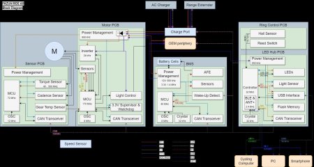
Originally I was planing to build an 18650 pack from scratch but unsurprisingly there's too much canbus communication between the motor and battery for this to ever work properly. I could potentially hook something up in parallel but really want to be able to run on internal battery or REX independently.
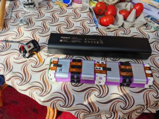
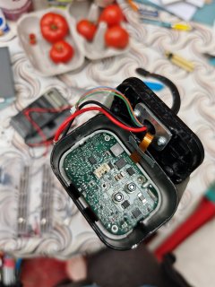
I've managed to get hold of 2 brand new energy 430wh fixed batteries fairly cheaply and have opened one up to look at the pack layout. I was pleasantly surprised to find that unlike the 250wh batteries for the ride 50 system (which caused quite the argument on this thread Fazua Battery Mystery how do you get 36V from 17 Batteries) this battery is wired up in the same format that it is packed. So the top side that you can see is 12x21700 cells in series end to end up and down all 3 collums. There is then another identical group of 12 underneath in parallel (with Nicole strips). The bms is a nice neat PCB on one end of the battery again unlike the older batteries which ran the length of the pack. Again unlike the old packs this one uses orange plastic ribbon cable type stuff with integrated metal traces acting as the wires. Pads on this are then spot welded to nickel strips on the cells. At first I thought this would be my downfall but actually it keeps all the wiring on one neat foldable sheet on one side of the pack.
To make a range extender with around 215wh was expecting to have to carefully strip down this pack to the individual cells and rewire in a new housing with but still with the original bms so that the motor gets all the right data and is still running on fazua tech. After discovering this layout of the pack I'm now thinking I might try to simply cut the parallel group of 12 cells off the back of the pack and then "fold" the remaining 12 back on itself in half to give a 2x3x2 format with the bms cable running up the middle between the cells. Then ideally I would refit it in the existing brackets and cut down the housing to half the length and fix it back inside
The problem with this is that there appear to be 2 threaded rods holding the pack together down the centre of the cells. I'm not sure whether the cells are actually welded/soldered together end to end or whether it is just the tension from these rods and the friction of the brackets that is electrically connecting the cells in series. I'm worried about loosening these rods and disconnecting the bms as I have read rumours that the bms in the ride 50 batteries will never come back to life if it is disconnected; something about the firmware being stored on RAM rather than EPROM which makes sense. Would there be any way to check whether this is the case with this BMS? Anything to look out for on the chips on the board perhaps?
The other problem with this is that the brackets are designed with a slight gap for the bms ribbon cable to run in down one side but not in the middle. I could probably adapt the brackets to allow this but even so the threaded rods would be in the way when reassembled, especially at the bottom where the cable will have to fold to come back up the inside. Hope this makes sense.
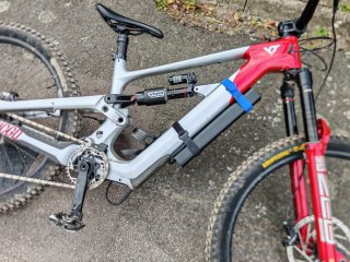
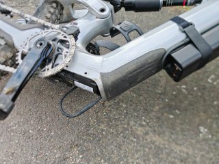
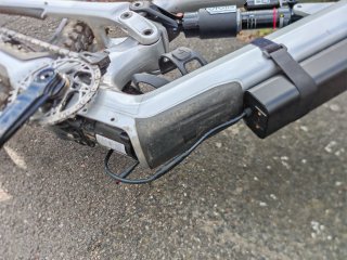
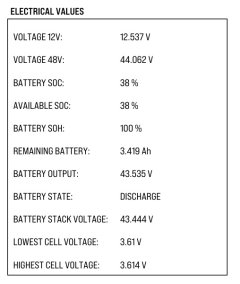
Anyway apologies for the long post, this is only the first step and this may not even work. I'd like to hope the bms will not be freaked out by the reduce capacity and will simply see it as an old high resistance pack with 50% of its original capacity. It should perform identically to an internal battery and as pictured I've already checked the motor is happy being plugged into a different battery (unlike mahle which needs reprogramming). I am doubling the load on each cell if cutting the parallel group out so after checking the current ratings I may avoid using the max assist level.
The next step if this works will be making some form of switch to switch between internal battery and REX. This will be relatively complicated as there are 6 wires from each battery (vbatt, 12v and canbus) and needs to fit inside the frame so may end up using some small mosfets.
Anyway we shall see but first any advice on getting this first prototype working is appreciated!!
I've never tinkered with ebikes before so apologies in advance for my ignorance but have built drones and therefore have experience with Li-Po batteries so thought I'd try building my own. Any constructive criticism or ideas are welcome as I want to do this the best way I possibly can and help anyone else looking into this as as far as I can tell no one has torn down a ride 60 battery.
Originally I was planing to build an 18650 pack from scratch but unsurprisingly there's too much canbus communication between the motor and battery for this to ever work properly. I could potentially hook something up in parallel but really want to be able to run on internal battery or REX independently.
I've managed to get hold of 2 brand new energy 430wh fixed batteries fairly cheaply and have opened one up to look at the pack layout. I was pleasantly surprised to find that unlike the 250wh batteries for the ride 50 system (which caused quite the argument on this thread Fazua Battery Mystery how do you get 36V from 17 Batteries) this battery is wired up in the same format that it is packed. So the top side that you can see is 12x21700 cells in series end to end up and down all 3 collums. There is then another identical group of 12 underneath in parallel (with Nicole strips). The bms is a nice neat PCB on one end of the battery again unlike the older batteries which ran the length of the pack. Again unlike the old packs this one uses orange plastic ribbon cable type stuff with integrated metal traces acting as the wires. Pads on this are then spot welded to nickel strips on the cells. At first I thought this would be my downfall but actually it keeps all the wiring on one neat foldable sheet on one side of the pack.
To make a range extender with around 215wh was expecting to have to carefully strip down this pack to the individual cells and rewire in a new housing with but still with the original bms so that the motor gets all the right data and is still running on fazua tech. After discovering this layout of the pack I'm now thinking I might try to simply cut the parallel group of 12 cells off the back of the pack and then "fold" the remaining 12 back on itself in half to give a 2x3x2 format with the bms cable running up the middle between the cells. Then ideally I would refit it in the existing brackets and cut down the housing to half the length and fix it back inside
The problem with this is that there appear to be 2 threaded rods holding the pack together down the centre of the cells. I'm not sure whether the cells are actually welded/soldered together end to end or whether it is just the tension from these rods and the friction of the brackets that is electrically connecting the cells in series. I'm worried about loosening these rods and disconnecting the bms as I have read rumours that the bms in the ride 50 batteries will never come back to life if it is disconnected; something about the firmware being stored on RAM rather than EPROM which makes sense. Would there be any way to check whether this is the case with this BMS? Anything to look out for on the chips on the board perhaps?
The other problem with this is that the brackets are designed with a slight gap for the bms ribbon cable to run in down one side but not in the middle. I could probably adapt the brackets to allow this but even so the threaded rods would be in the way when reassembled, especially at the bottom where the cable will have to fold to come back up the inside. Hope this makes sense.
Anyway apologies for the long post, this is only the first step and this may not even work. I'd like to hope the bms will not be freaked out by the reduce capacity and will simply see it as an old high resistance pack with 50% of its original capacity. It should perform identically to an internal battery and as pictured I've already checked the motor is happy being plugged into a different battery (unlike mahle which needs reprogramming). I am doubling the load on each cell if cutting the parallel group out so after checking the current ratings I may avoid using the max assist level.
The next step if this works will be making some form of switch to switch between internal battery and REX. This will be relatively complicated as there are 6 wires from each battery (vbatt, 12v and canbus) and needs to fit inside the frame so may end up using some small mosfets.
Anyway we shall see but first any advice on getting this first prototype working is appreciated!!