• Hello ES! We could use some help to get us past the finish line on building the new knowledgebase for the forum.
    Can you donate? Please see our fundraising page. Thank you!

Fazua motor teardown

PaulD

Regular
Joined
Aug 28, 2008
Messages
430
Location
Ashland, OR, USA
I had the opportunity to open up a Fazua Ride 60 motor to investigate a motor noise issue. Much like the EP8 motor I worked on in a previous thread, this was not easy. These OE motors are not designed to be simple to work on. I designed 4 custom tools just to open the case and remove the spindle assembly. Unfortunately, I can't see any way to get the planetary gearbox and motor out of the case without excessive force. The customer got a warranty replacement, so this motor doesn't need to be returned, so this is more of an educational exercise.
One of the problems with these OE drives, is that they are very difficult to test without the right diagnostics tools from the manufacturer. I can't even test anything without a complete bike hooked up to it with the OE battery, display, etc.
Initially, I thought it would make sense to remove the spindle assembly first (EDIT: don't try to remove the spindle before the motor side of the case. The torque sensor blocks removal of the spindle, and will get damaged (see cracked die casting below))
1744235896283.png
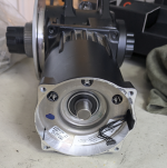
This is the where the controller goes, and the phase connectors mate. The pigtail goes to the torque/cadence sensor. It looks like it uses a magnetic encoder.
1744235968348.png
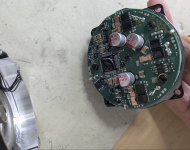
This is the controller board. Very compact.
1744236114283.png
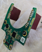
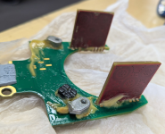
Backside of the torque sensor board. The red boards I think are wireless transmitters/receivers for the torque sensor.
1744237140479.png
Otherside:
1744237179545.png


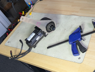
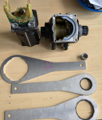
These are the custom tools. The small one is a custom socket to remove some unique pins that hold the 2 parts of the case together. I had to get it 3D printed in steel. Let me know if anyone wants to borrow it, or have the CAD files. This also shows the helical bevel gears... No sign of wear, but i think the mileage is pretty low on this drive.
1744236451997.png

Just making sure the bearings and gears don't sound bad by spinning the motor up with an external controller. No obvious bad sounds. The grinfineon controller I'm using struggles once the ERPMs get too high, so I can't spin it any faster at the moment.

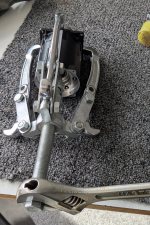
Attempting the excessive force method for removing the motor/gearbox. No dice.
1744236317236.png
 
Last edited:
Quick update. The gearbox came out just by pulling really hard :rolleyes:
1744329511684.png
A closer look at the aluminum ring gear and plastic planet gears. Fine 0.7M gear teeth
1744329575896.pngAnd the bad news is that the motor WILL NOT come apart. Perhaps it's potted or glued in some way, but I managed to damage the case with the gear extractor. :cry: I could certainly cut the case apart to have a look, but I'll save that for another day.
 
Thanks Paul. I have a broken FAZUA ride 60 motor (warranty replacement) and I was thinking open it up. I see it’s not an easy task 😅. Apparently this unit is made in some way that you can’t repair it🥲

I’ll be waiting for updates.

Cheers!
 
Hi Paul,
Great pics and descriptions of the teardown! I have a question about the BB spindle. Can the spindle be removed from the housing. Or does the motor assembly need to be removed from the BB spindle assembly? I have issue where the drive-side lockring sheared off the chainring spider. The locking threads are still in the motor. The space between the BB spindle and splined chainring spider ring is very tight. I'm wondering if you have insights on removing the spindle or getting the lockring threads out of the motor? Thanks in advance! 1000000980.jpg1000000979.jpg
 
Hi Paul,
Great pics and descriptions of the teardown! I have a question about the BB spindle. Can the spindle be removed from the housing. Or does the motor assembly need to be removed from the BB spindle assembly? I have issue where the drive-side lockring sheared off the chainring spider. The locking threads are still in the motor. The space between the BB spindle and splined chainring spider ring is very tight. I'm wondering if you have insights on removing the spindle or getting the lockring threads out of the motor? Thanks in advance!
The spindle can be removed, but the motor assembly and torque sensor need to be removed first! Otherwised you'll damage the sensor. I would suggest not taking it apart if you can avoid it.
If I were you, I'd make some kind of tube shape tool with the ID slightly larger than the spindle and the OD slightly smaller than the ID of that splined drive flange. Perhaps you can just find a tube of those dimensions... then cut some grooves in the end of the tube to help grab the piece that broke off of the lock ring. Let us know how it goes!
 
Thanks for the detailed write-up! People are having issues with the spacer under the big 4-notch lock ring getting loose and the motor failing shortly after. Do you know what the purpose of that lock ring is? Or that weird spacer?
 
Thanks for the detailed write-up! People are having issues with the spacer under the big 4-notch lock ring getting loose and the motor failing shortly after. Do you know what the purpose of that lock ring is? Or that weird spacer?
The spindle assembly is threaded into the housing, and the lock ring (is supposed to) prevent it from moving. If it gets super loose, it could damage the torque sensor from the spindle moving too far sideways.
 
Good to know, seems like keeping that spindle tight is important. I looked at mine and the lock ring is indeed loose. I'm going to start the warranty process, but I'm on a quest to learn how to keep this motor maintained so I can ride it for as long as possible. I wonder if others might want to buy that tool you made? PXL_20251129_001143910.jpg
 
I can send them to you if you promise to send them to the next person that needs them.... or I can post the files somewhere and people can get their own laser cut and (metal) 3D printed.
 
I appreciate it, but don't need it just yet. Definitely post the files! Thingiverse is a good repository, just need to upload a 3D model file along with the cad file.
 
Hello! Just found this post. Good to know that someone has tried to take this drive unit apart. I've been trying to take one apart myself but don't have the necessary tools. I found this pictures online a while ago and read somewhere that the poster had found someting loose inside that could be retightened.

Did you find anything loose? Care to share the exact order in which you took it apart?

Hopefully we can get somewhere.

CheersWhatsApp Image 2025-09-24 at 16.34.20.jpegWhatsApp Image 2025-09-24 at 16.39.34.jpeg
 
Paul - these tools are awesome. I had a set of the wrenches laser cut via sendcutsend in basic aluminum. For those who would aim to do the same, for the large 4-lobe wrench I used 4.7mm (0.187") 5052 H32 aluminum, and for the other wrenches, I used 3.2mm (0.125") aluminum. I skipped all the post processing steps like deburring, expecting that I'd need to do some file fettling anyway. (I did) - the laser cutting is accurate, but not as precise as we'd like for a tool. A cheap set of needle files from Harbor Freight and 15 minutes of try/file/try again make some nice fitting wrenches.
For convenience, I've borrowed Juan's photo from above to call out the parts that I'm referring to, and I'll be pedantic and use the names throughout my description:

FazuaR60Parts.png
In my case, my motor had developed a knocking/creaking sound over the course of a single ride. Inspection showed that the stainless locking ring was completely free. It was no longer pinched between the gearbox/bottom bracket housing and the 4-lobe bearing carrier, similar to the image in eleazar6's post above. Every image of the drive unit that I could find shows that lock ring pinched between the 4-lobe bearing carrier and the gearbox housing. For the life of me, I can't figure out how it's supposed to keep the 4-lobe bearing carrier from unthreading as it doesn't lock against anything on the housing or the frame of the bike, and when pinched between the two parts it doesn't stop anything from unthreading. The images of the drive unit that I've seen show the locking ring in this orientation relative to the 4-lobe, pinched against the case:
Fazua 3.png

it would seem like it would lock things in place nicely if it were slipped over the 4-lobe and then the locking 'nubs' engaged with one of the mounting bolts, but it's not designed that way as the mounting bolts are too far away radially from the axis of the crank spindle for the ring to engage with them.

Fazua2.png


Anyway - in my case, slipping the locking ring back between the 4-lobe carrier and the housing, and rotating it in tandem with the 4-lobe until the assembly was finger tight, then snugging that down with the 4-lobe wrench that Paul designed, reinstalling the drive unit after cleaning all the bolts and threads of thread locker debris, then applying new Loctite 243 and torquing to spec, letting it cure overnight, and then recalibrating the motor this morning has solved my knocking noise problem. I don't know how long it's going to solve the problem in the absence of a way to secure that 4-lobe against backing out, and it certainly didn't feel like there was thread locker applied on the threads of the 4-lobe. If it backs out again, maybe I'll go down that road. If I do - I'll update this thread. I hope that this helps someone.

-DrewmanBeing
 
Paul - these tools are awesome. I had a set of the wrenches laser cut via sendcutsend in basic aluminum. For those who would aim to do the same, for the large 4-lobe wrench I used 4.7mm (0.187") 5052 H32 aluminum, and for the other wrenches, I used 3.2mm (0.125") aluminum. I skipped all the post processing steps like deburring, expecting that I'd need to do some file fettling anyway. (I did) - the laser cutting is accurate, but not as precise as we'd like for a tool. A cheap set of needle files from Harbor Freight and 15 minutes of try/file/try again make some nice fitting wrenches.
Great write up! Glad you were able to solve the issue. Let us know if it holds up!
Yes, the tools do require a bit of touch up with files. I erred on the side of tightness when designing them, knowing that laser tolerances could potentially be not quite good enough.
 
Has anyone else made any further progress?

I got the tools and spare motor shown in the pictures from Paul but haven't had the chance yet to take another motor apart.

In my opinion the plastic helical gears with their fine teeth could be a point of failure. Will know this when I take another motor apart which had a loud grinding noise.

Anyone know if or where this helical gears could be manufactured or bought?

There also seems to be a ratchet clutch in the main spindle that could also be a point of failure IMO.
 
Last edited:
I wonder if the "locking ring" is a shim. I have an issue where when once the unit warms up it develops drag. It feels like a angular contact bearings that's over tightened. I could see a case where the 4 lobed ring is tightened to set bearing preload or to adjust backlash of the ring and pinion. The gap between the nut and housing measured then slightly loosened and having the locking ring/shim installed and torqued. It would be easy for the factory to have shims of different thicknesses they swap in as they verify turning torques and gear noise/patterning.
 
Back
Top