BAFANG M215 (BBS01 CAN bus), M315 (BBS02 CAN bus), M510, M560, M820, CR-A101 FOC Open Source EBiCS Firmware for GD32F303 processors

And yep brakes are essential in a test setup on the road.
I can publish a first release without having tested on the road myself, but of course there is a certain risk, that the firmware shows a major bug. Is anyone interested in being a guinea pig?
 
As a request, we need to be able to read the temperature of the motor on the display to check on over amps and poor efficiency, is this possible.?

Great news on getting the first Beta available. Unfortunately I’m out of the U.K. at the moment and can’t help on testing. Will be back in a few weeks.
 
we need to be able to read the temperature of the motor on the display to check on over amps and poor efficiency, is this possible
No problem in principle, if the M510 has an NTC on the motor windings. But I have to identify the ADC input pin for that. Any idea which pin carries the NTC information on the PCB connector? I guesss this is the right one, but which of the six pins? :unsure:
IMG_20260205_183956_643~2.jpg
 
Last edited:
It looks like Bafang changed numbering of those pins or maybe flipped the connector on PCB. On M560RS the numbering is different. I do not know if the connector on your picture is flipped or if they just changed the numbering.

1770315585932.png

Regarding the connector locking tab orientating here are the pins for the 20K NTC Thermistor. The pins on the thermistor leads connector should be the same for all the motors in regard of the locking tab location. You have to check where the tab is to find out the pins (but if you have the motor just see where the leads are connected).

1770315918450.png

By the way, for same reason Bafang uses wrong numbering for the pins. The 1st pins is indicated on the connector with an arrow and correct numbering order described in the connector manufacturer documentation (and they follow the common numbering order for such connectors), but Bafang numbered those pins differently on the PCB for some reason.
 
Last edited:
You have to check where the tab is
This is really strange. There are only 3 pins connected on my PCB. GND, +5V and one signal. Three pads (1,2+4) have no traces on the PCB.

1770320547867.png
1770320615912.png
1770320685180.png

I followed the trace via some ferrite balls and resistors to pin PC4, which is ADC channel 14. So I can implement the temperature reading now.

1770322721073.png
 
Last edited:
I do not know which pin is for signal and which pin is for ground on the Bafang PCB. I only know which pins are for the thermistor. There are only 2 wires connected to 2 pins on that connector. 5V pin is not used, it is there for nothing (or maybe to trigger an error in case of user connected PAS sensor to the temperature sensor receptacle). Just signal and GND are used on that temperature sensor connector.

On the LUNA controller the pin #3 (from you picture) is connected to 3.3V voltage divider circuit (the thermistor is part of the voltage divider circuit) and to MCU through some resistors. The pin #5 (from you picture) connected to GND. On the Bafang controller it might be swapped and operate with different voltage, but I do not know details about it.

1770332829908.png
 
Last edited:
I followed the trace via some ferrite balls and resistors to pin PC4, which is ADC channel 14.
Hm, strange. The voltage on this pin does't change with the temperature. The pin PA4 changes. But that pin is also the one that reads the on/off button. So it has a dual function?! I can't really believe it, because the measured value also changes slightly with the battery voltage, so it's actually unsuitable for temperature measurement?! Maybe it is just a temperature drift of the resistors on PA4? :unsure:
Or this is a dual safety function, the controller switches off on low battery and on overheat?!

ProcessorPinoutM510.PNG
 
Last edited:
Correct me if I’m wrong here. The on off button pulls down to only 1/2 voltage to signify the on call from the button on the M510. When connected to say BESST it pulls that line fully to ground to signify BESST is connected. Is this the dual function you are talking about ?
 
I looked at a not so good picture (grabbed from a GBK video) from a M510 board and it seems you have located the ground and signal wire from the 2 wire temp sensor at the correct pins in the 6 pin connector. Maybe by trying to follow the signal trace via some components you ended up on the wrong pin on the processor?
M510 temp sensor 2 wires.png
 
Maybe by trying to follow the signal trace via some components you ended up on the wrong pin on the processor?
Yes, I had more than one error in it :)
First, the trace ends in PB0, not in PC4.
Second, I've configured PB0 as digital output, so the processor pulled it to Gnd by default.
Now I have to find the right linearization for the temperature signal....
 
Last edited:
I can't test it on the road, as my test bike has no brakes yet.
After installing the brakes, I did a very first short test ride on the road today. (It's dark and rainy in Bavaria 🌧️) The assistance is not as smooth as I know it from my hub motors, so I have to increase the filtering of the sensor data, or try a completly different algorithm.
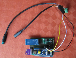
But first, I will build a bluetooth transmitter, that sends my CAN debug data to my cell phone. Then I can see much better, what's going on in the motor and battery current control....

regards
stancecoke
 
But first, I will build a bluetooth transmitter, that sends my CAN debug data to my cell phone.
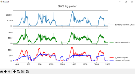
Done. The first test ride shows that there is an oszillating value for the human power, when decreasing the torque on the crank (marked red in the graph). I have no idea what's going wrong there at the moment, must have to do with the cadence signal, I haven't logged it yet.

You can see the battery current limitation in the green marked area. The current is plotted in ADC values, so no physical unit.

1771078812434.png

Here some information on the Bluetooth sniffer. It is plugged between the controller and the display, just like the Canable.

1771078989412.png


1771079345690.png

The firmware for the Bluepill is at github:
https://github.com/stancecoke/BionX_Minimal_Translator/commits/BAFANG_Hubmotor_Controller/
 
Last edited:
I have no idea what's going wrong there at the moment
I've improved the algorithm to calculate the human power. Now it looks much better. But there seems to be a bug in the cadence calculation, the values are to low. I have to rethink the formula :)
The new M510RS/560RS quadrature sensor is optical and have more pulses per revolution.
I think, @TPEHAK mentioned the number of pulses for the M510 somewhere, but I can't find the post.
It's raining outside, so I won't do further test rides today. 🌧️

1771085330184.png
 
Last edited:
But there seems to be a bug in the cadence calculation
I've calibrated it for 20 pulses per revolution on the PAS1 pin now, that's 40 pulses on the speed/direction wire, that seems to be not connected on my hardware.
I did another testride this morning, it seems that on a 36V battery the maximum cadence where the motor can deliver noticibale support, seems to be quite low, I couldn't even get the 12 amps battery current, that I set as max limit on riding uphill with high cadence.... There are really many things to be tested, but I did a very first pre-release for the M510 with bootloader3 anyway. Maybe someone is brave enough to test it. Any fedback is highly welcome...
There are no limits for the settings, so don't blame me, if you kill your motor or your controller by setting current limits, that the system can not handle ;)

 
Last edited:
Us humans can't exert much torque at higher cadences within the rotation of the pedals, you may want to check / record just how much the torque sensor is being activated before looking elsewhere ?
 
how much the torque sensor is being activated before looking elsewhere ?
The motor current setpoint is calculated from the human power. As you can see, this peak in the human power does't lead to a peak in the motor current, while the 12 amps battery current aren't reached. I guess, the duty cycle is already at maximum, so the battery voltage is not able to push more current... I haven't logged the duty cycle yet, to confirm that. As I said, there are many things to be tested, but it's cold outside, doing test rides is not very much fun at the moment ;)

1771156125079.png
 
I haven't logged the duty cycle yet
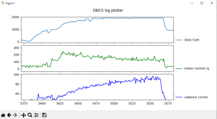
I've done another testride, the maximum duty cycle (max is set to 1920) is reached at about a cadence of 80/min (if my scaling is right now) The motor current drops with higher cadence, as the BEMF gets higher and the battery voltage can't push the amps against it any longer.

Of course, you have to remember, that with FOC you can't get to a duty cycle of 100%, as you need some time to sample the phase currents. I limit it to about 94% at the moment, maybe with the M510 I can get a little higher before the current reading gets scattered. I found this 94% with the Shengyi middrive and the hub motor controller.

1771164444680.png

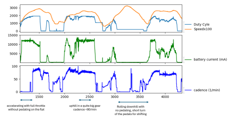
On the next test ride, I've accelerated in a big gear with full throttle, without pedaling. There you can see the 12A battery current limit is reached easily. Then I climbed a bridge at a cadence slightly lower than 80/min, so the battery current limit was reached with maximum duty cycle.
With 36V (10s) the M510 is nothing for people like me, that prefer a high cadence. I don't have a 48V (13s) spare battery lying around, so I can't test with 48V. This will perform much better, I guess.

1771169514438.png
 
Last edited:
on 52v the standard M510 seems to be able to spin pretty freely well over 110rpm. I tend to ride in that 90’s cadence and it’s a nice engine for that.
 
I'm not experienced in mountain biking, my main usecase is communting in the flat. So I don't know, how the assistance should "feel"on a steep, rocky single trail. I've added the possibility for setting the torque signal filter by the user now. The field "Acceleration" from the "Assist (Full)" tab of the Canable tool is used to define it per assist level. Maybe the word "level" is not the right word any longer, the word "ride mode" is better, as you can set a completly different behaviour for each mode :cool:
I've done a test ride with different filter settings and constant assist factors to show the effect: With filter = 0 you get a direct output from the torque signal to the motor current setpoint, just as you would press the throttle with your legs. This leads to a very responsive power distribution of the motor, but of course the power will pulsate with each crank stroke. The higher the filter value is set, the smoother, but more sluggish the assisance gets. The graph shows an acceleration from standstill for the filter settings 0 to 4. This feature is not in the release yet.

1771263163312.png


AssistFullTab.JPG
 
Last edited:
Back
Top