BAFANG M215 (BBS01 CAN bus), M315 (BBS02 CAN bus), M510, M560, M820, CR-A101 FOC Open Source EBiCS Firmware for GD32F303 processors

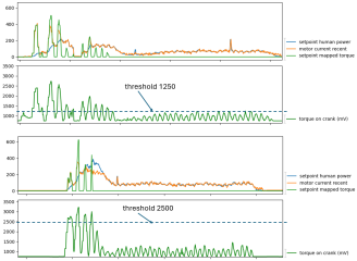
I've added the next feature, the torque override for having both, fast reaction if needed and smooth assitance for cruising.
You can define a torque override threshold for each mode now. The motor current setpoint from the override feature is mapped from the threshold to the max torque (3300mV) to the range from zero to max motor current. This means you can decide for yourself whether you want this “kick down” only when you press the pedal very hard, or every time you accelerate. As I don't like this behaviour, I will set the threshold to 3300, so it will never kick in :)
1771437718880.png

1771361630548-png.384637
 
@stancecoke don't worry, somebody will try it out! It's an amazing piece of software. I will try it as soon as I'll be able to get a second hand m510 motor for testing. I already have a frame.
 
I've spend two days now, to analyze the brake circuit. On my motor the signal line of the brake connector always stays on 0V. On a spare controller I get 3.3V on the connector pin. There is a safety circuit on the PCB that pulls the line to GND in case of a malfunction, obviously. But I was not able to find, what is driving the base of the transistor, that pulls the signal down :confused: Any ideas?!

Of course I can implement the brake signal in the code, but then my motor will not run any more until I find the reason, why the signal is pulled down....

1771611652816.png
 
Last edited:
Пока никаких отзывов нет.:(
Чего-то не хватает? Стоит ли мне написать инструкцию по использованию прошивки? Мне казалось, что скриншоты в файле ReadMe репозитория достаточно понятны...
Hi! I'm waiting for my M510 to arrive from China. It's Spring Festival there, so shipping is delayed. The reason for its limited popularity is the Canable Pro (IMHO). Not everyone understands that you can just buy a ready-made board and connect two contacts. I personally use BESST more often because it has enough features for official firmware. The rest is closed to changes.
 
I personally use BESST more often
I have no BESST, so I can't try, if the firmware update works with it also. But it should work, as the Canable Tool does the same as the BESST.

I can't understand, why people buy an original BESST for a lot of money, if you can get the Canable for 30€ or even less, if you solder yourself. And have no trouble to tweak the Online Check of the BESST tool, if you are not an official Bafang dealer...🤷‍♂️
 
I personally use BESST more often because it has enough features for official firmware. The rest is closed to changes.
I personally use canable pro more often compared to besst pro. And you are right, some settings that people like to change are locked but not on all controllers... Those can then be changed with canable pro but not with besst pro.

Canable pro gives more insight regarding firmware. You can spot with canable pro differences in firmware which you can't with besst pro. Say you have 2 firmware files...
Just one example, with canable pro it shows for one firmware max motor RPM 4000 and for the other 3000RPM.
In canable pro at the controller tab you have a lot of info regarding controller and motor settings which can not be get with besst pro. And that info / settings, no matter if you can change it or not, it gives you insight in differences between firmware for the same controller.
 
But I was not able to find, what is driving the base of the transistor, that pulls the signal down
Strange finding: I've flashed the original 36V Bafang firmware to my bike, now the brake signal line shows 12V when idle o_O
With the original 48V firmware it showed 0V at about 37V battery voltage, I thougt this might be a hardware defect, but obviously it depends on a certain digital I/O pin setting of the processor. :unsure:

edit:
after a lot of trial and error: Pins PB3 and PB10 have to be high, to get the 12V on the brake line. Strange...
 
Last edited:
I looked at another totally different, (43V) controller. (Sorry i used your picture to change, with ahum, with Windows Paint).
Took some time because components are on top and back side of the pcb. Difficult to measure the correct processor pins if needing probes on both sides of pcb.

BRAKE circuit M400 CAN 43V.png
 
In my picture it says "maybe 5V" that is correct, it is fed by voltage regulator 5V.
I connected the controller to power supply, expected smoke but amazing, it still starts up. In the past I had cut the phase wires, hall sensor wires, torque sensor not connected, no speed sensor etc.
I connected via an 1T4 cable the display, a brake handle and canable pro.

On the brake line input i have 4.7V and engaging brake handle it changes to 0V. Canable pro on "sensor tab", the controller state number = 8 obviously there are no hall sensors anymore. When engaging brake handle "controller state number" changes to 3 = OK telling brakes are on. On the DPC080 display there seems to be no symbol for "brakes are engaged".
I wonder under which circumstances the processor decides to enable the "safety signal".
Maybe rekrezeb has a seen something related to that in firmware 820?
 
Last edited:
On the brake line input i have 4.7V and engaging brake handle it changes to 0V.
My spare M510 controller seems to be a different hardware revision than the controller on my bike. I got the brake lever switch working now, but the signal is on PC0, not on PC13 😵‍💫 The Canable Tool shows the same hardware info for both firmwares that I dumped from the two controllers. :unsure:
Can someone confirm the 12V on the signal wire of the brake on his M510? It's quite unsusual, I think. 5V or 3.3V are most common...
I get the 12V when I'm flashing the orignal Bafang MMG522C3619F802008.1-CR X10N.510.FC 2.0 20240131.bin firmware, measured on the open brake connector.
 
Last edited:
Next strange finding: I can't set PB3 high, if I start the system without the bootloader by switching the system on with the display.
When I start a debug session, so the system goes through a software reset, it works. If I start the system by the display with the bootloader installed, it works also. So the bootloader does something "magic" that I don't understand yet. This doesn't matter for users who flash the firmware by the Canable/BESST tool, as there the bootloader is present.
Nevertheless I have published the pre-release v0.002 with the latest features:

There are some current spikes in my latest log. Maybe they are caused by misreadings of the rotor position from the encoder, perhaps we need a plausibility check, to ignore obvious misreadings. But they didn't throw the fuse, so they are acceptable for me at the moment.

1771783023627.png
 
Last edited:
Can someone confirm the 12V on the signal wire of the brake on his M510? It's quite unsusual, I think. 5V or 3.3V are most common...
Stancecoke I’ll check my wiring tomorrow night if that’s OK, I know the light output is 12volt, is this what you are looking at ?
 
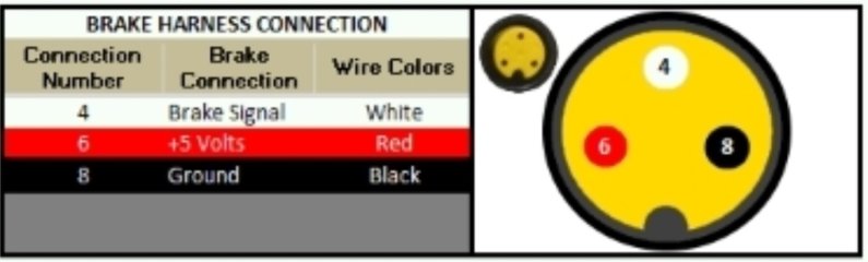
Update, went out to the bike and fitted a battery which had been on charge after a very muddy and long wet ride today. On the brake cutout connector ( yellow and round ) is 3 pins. 0v on one and 5V on the other two. Could I presume that the two 5 volts pins are for two independent front and rear brakes ? Hope this helps.

So it’s the light connector that is 12 volts.
 
Last edited:
@ stancecoke
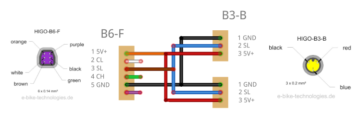
I guess that is the wrong one... I don't have M510 but i believe if you need brakes sensors for that one you need the purple connector on the motor. That one should have the brake signal input. The cable you show is 4 in 1 but plugged in M510 the display connector will be correct, also throttle i believe, but that M510 port where it plugs to carry the 12V for the front light. So the only? wire they could use for feeding that front light is the one that is normally for the brake sensor. So if you plug a 4 to 1 cable in that M510 port changes are indeed you get the 12 volt for the front light on your brake plug.M500 M600 Frontlight-display-throttle.png
Picture above is display, throttle, frontlight.
Picture below is brakes
Bafang_M500_M600_Brakes_Cable.png
Picture below is purple connector on motor (downloaded from this forum)
M500-600 purple connector.png
 
Last edited:
OK, yes. But then this cable from Windmeile is weird. I just checked the connection of the middle pin. It's the middle in the lower row of the 8pin connector. So that's the headlight indeed. Good, that it seems to have a short circuit protection, otherwise I would have destroyed the light supply....

1771794344458.png
 
That cable from Windmeile you have should work fine all functions when connected to a BBS01B canbus and certain CRS10F hub controllers and maybe others.
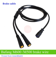
Below is a Brakes cable that is used for M500 and M600 and others using purple plug . (Picture taken from greenBikeKit)

Brake cable, M500 - 600 and others.png
 
OK, yes. But then this cable from Windmeile is weird. I just checked the connection of the middle pin. It's the middle in the lower row of the 8pin connector. So that's the headlight indeed. Good, that it seems to have a short circuit protection, otherwise I would have destroyed the light supply....

View attachment 384861

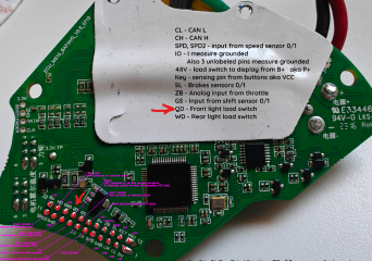
On the Luna controller I marked that QD pin as BRAKE because of the Luna controller PCB shortens that pin with the brake signal. But I just checked the Bafang M560RS controller and those pins are not shortened. I believe that pin suppose to be power for the light (probably front light) on the Bafang controller.

Maybe Marcos did it to use the front light connector for brake to not connect extra wires and use just one harness, but on the Bafang controller that pin seems to be dedicated for the light power.

1771799353390.png

1771798562386.png

I also do not know why your harness has brake connectors. Green Bike Kit does not offer any harness with brakes connectors for that display receptacle for those motors. Maybe Luna used same cables and it is a cable for BBSHD the new Luna controller is based on and it was the source of the confusion or the reason they did it this way, but it looks like Bafang M600/500/560/510 do not use that cable and it looks like there is no brake signal on that receptacle on those motors at all


It looks like brakes and display should be on two separate harnesses for those motors connected to different receptacles.
 
Last edited:
I believe that pin suppose to be power for the light (probably front light) on the Bafang controller.
Yes, it seems @DPC18RI is right, that Bafang uses different pinouts on this 8pin display connector for different controllers.:eek:.
Doesn't matter, then I found how to switch the lights accidentally. The brake function will be on PC13 then, as I found on my spare controller :)

I found this image from @Tomblarom also. But this is completely different :eek:
1771835691818.png
 
Last edited:
That picture from Tomblarom is correct in my opinion. It's another variant. In this variant that yellow triangle 3 pin connector is for connecting the canbus lines from a bafang battery. You could use that cable on BBSxx canbus and some hub controllers which have the opposite 8 pin trapezium connector bungling out.

In my opinion, i believe this particular cable from the picture above is not for the M510 version you have. (It wil work but you will have again 12V on that brake connector if you press the "lights" on button on the display).

Windmeile has a cable which should fit M510. Cable has frontlight, display, battery canbus connector but this variant has no throttle connector.

The other cable which should fit M510 has rear light and connector for speed sensor. If i remember well, ( if you don't need rear light) for speed sensor you can have also one with 8 pin connector direct plug to motor . There is also speed sensor with 4 pin blue plug that then will fit in the mentioned Windmeile "rear" cable. Another variant for "rear" cable is one with rear light, speed sensor, and shift sensor connector... ( I can be wrong because i typed from memory and i'm not so young anymore lol).

Doesn't matter, then I found how to switch the lights accidentally.

(y)
 
Hm, this offer at AliExpress says, the harness is suitable for M5x0/M6x0 ... also ;)
Windmeile says they've tested it, the brake lever on the 3pin female connector stops the motor....
It's not a bug, it's a feature :ROFLMAO:
But of course this image is wrong in the hubmotor classification also. The harness works on the CAN hubmotor controller for sure. There the wires for the lights are not on the harness, but on the controller directly.

1771843647217.png

1771848239083.png
 
Last edited:
Back
Top