Gear sensor for universal controller?

Cyclomania

10 kW
Joined
May 22, 2022
Messages
659
Location
Northern Europe
I wonder if someone here knows if there exists a universal gear sensor for non bafang controllers?

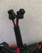
Bafang has a neat shift sensor that makes the bike not give power to the mid drive motor while pedaling. This does not exist for universal controllers as far as I know? But I would like to know if there is something similar to this for universal controllers or a similar solution? So that the mid drive does not run on the exact moment of pedaling.

Thanks
 
If the controller has a brake sensor input then it should be compatible with a gear shift sensor as you can wire brake and gear sensors in parallel to a single input.

If any of them close the circuit then the motor power is cut.
 
If the controller has a brake sensor input then it should be compatible with a gear shift sensor as you can wire brake and gear sensors in parallel to a single input.

If any of them close the circuit then the motor power is cut.
Hmm this sounds like a neat idea. Any thread on the subject here form someone who has done it?
How would that work? Brake sensors are often driven by a magnet and when the magnet gets far enugh away form the sensor it cuts power. Maybe it would be possible to do something similar with the shift sensor.

For example put a brake magnet on it.So when you press the shift lever the magnet gets further away and the sensor cuts power. Maybe something like that ?
Or what did you have in mind exactly?
 
In two wire sensors that don't require power, they are just normally open switches that close when activated. So they will work in parallel with a single pull up/down brake input when connected in parallel.

If the input is pull up, then the brake/gear inputs connect in parallel to 5v and the input (if pull down they connect to gnd and the input) then if any close the circuit the controller cuts motor power.
You have a video or something of this?

I am thinking kind like this video but instead putting it on the shift wire ? What do you think?

Only thing is I do not like to have an open gear wire exposed to the elements. So I would have to cut something to fit snug in there. Kind of like the Bafang shift sensors if you have seen those?
But instead with some small metal type interface like he uses in the video. But only hooked up to a small part of the entire wire. So it never is opened in the middle completely to expose the wire.


Or did you mean that if I have two brake sensors I will instead solder on an extra cable to one of them? So that one of the shift levers is hooked up to two cables? One going to the brake on one side. And the other going to the shift lever?
 
Last edited:
I'm talking about using a prebuilt gear sensor that goes inline in the cable, like this.

Assuming that works like mine (seems it's a hall sensor version, so needs power - but active is still low) -

you connect the sensor 5v (red) wire to 5v supply, sensor ground (black) to ground. The signal wire goes to the (active low) brake sensor cutoff input on the controller.

Then any brake sensors are wired (if they are two wire) in parallel to the ground and brake sensor input on the controller.

If they are three wire then they are wired like the gear sensor, again in parallel.

So if any of those sensors pull the signal line low to ground - the controller will cut the power temporarily
I understand part of the process I think. Do you have a picture from you or someone else that has done this before perhaps? So I can visualize it in my head
 
just to add - if you wanted a second brake sensor - that would be connected in the same way as the first, same goes for another gear sensor.
 
View attachment 354985
There you go, quick example connecting a 3 wire gear and two wire brake sensor to a single input on the controller
My two break sensor connectors from the controller looks like this. Do you mean that the gear sensor should also be hooked up via the ground and red cable from the battery mount? Or do you mean the ground and red cables from each brake sensor?
 

Attachments

  • brake sensors.png
    brake sensors.png
    1 MB · Views: 3
nothing should be connected to battery voltage!

You can see on the diagram I drew for you - the blue blobs indicate where wires are connected.

So you connect the grounds all together and connect to gnd on the controller, you connect 5v from the controller to the gear sensor 5v, you connect the signal wires together and connect to the input.

Don't guess based on wire colour, ideally test with a multimeter so you know what it's doing...

You also need to confirm that the gear sensor you have is 'low active' - connect gnd, 5v to it and measure the signal when the gear cable moves. Mine shows about 1.3v when the cable is static, dropping to 0v when the cable moves.

You also need to make sure you're connecting them to a 'low active' brake sensor input on the controller. Some controllers have two brake inputs - one high, one low.
 
Last edited:
You can see on the diagram I drew for you - the blue blobs indicate where wires are connected.
Ah but my output looks a little bit different from that one. I have two brake sensor outputs from the controller looking like these pictures. In your picture it looks like there is three in total from the controller side. But I have two for each brake sensor so four in total. So I am not really sure which is my signal wire or if I actually have one.

But I guess then the wiring could be similar but slightly different but without a signal wire(?)

Not sure if you perhaps drew that picture thinking I had a different cable setup going from the controller side ?
 

Attachments

  • pic4.png
    pic4.png
    471.3 KB · Views: 10
  • pic6.png
    pic6.png
    140.4 KB · Views: 9
Ah but my output looks a little bit different from that one. I have two brake sensor outputs from the controller looking like these pictures. In your picture it looks like there is three in total from the controller side. But I have two for each brake sensor so four in total. So I am not really sure which is my signal wire or if I actually have one.

But I guess then the wiring could be similar but slightly different but without a signal wire(?)

Not sure if you perhaps drew that picture thinking I had a different cable setup going from the controller side ?
It’s a schematic diagram not a wiring diagram. There are no “ connectors” in the diagram. You need to grab a 5v source from the controller to supply the power to the sensor.
 
exactly - as E-HP said, it's not a specific wiring diagram for your situation - you'll need to do some work to get what you want working. I am not familiar with your controller. I'm giving you the information you need to get most gear/brake sensors working with most controllers.

Chances are the two brake connectors coming out of your controller are wired together - you can confirm that with a multimeter - I bet that pin 1 on brake sensor 1 is connected to pin 1 on brake sensor 2. ditto for pin 2.

so you can probably connect one or two brake sensor to one connector - and then you can connect the gnd and signal for a gear sensor to the other connector. But you will then need to find 5v somewhere on your controller to power the gear sensor.

it's very likely the PAS and/or Throttle connectors will have 5V for instance.
aha. I will investigate.
 
I do have this gear sensor that I was thinking about hooking up/splice to the brake sensors somehow. Only thing is I am not sure how to do it or if it is possible on this controller(?), now that I have investigated a bit and checked out the cables.

Since the two break sensors have two cables individually, four in total, but my gear sensor instead has three cables, I am not sure where I should hook up the third cable from the gear sensor? Should this be hooked up to the halls as well or something? Or what do you think could be a solution here Beemac?

Any ideas? Looks like this. This is the new problem that arose that I was not aware of. But perhaps that thirs cable can be hooked up somewhere else on the controller?
 

Attachments

  • pin2.png
    pin2.png
    1.1 MB · Views: 5
  • pin.png
    pin.png
    1.3 MB · Views: 5
Last edited:
Chances are the two brake connectors coming out of your controller are wired together - you can confirm that with a multimeter - I bet that pin 1 on brake sensor 1 is connected to pin 1 on brake sensor 2. ditto for pin 2.

so you can probably connect one or two brake sensor to one connector - and then you can connect the gnd and signal for a gear sensor to the other connector. But you will then need to find 5v somewhere on your controller to power the gear sensor.

it's very likely the PAS and/or Throttle connectors will have 5V for instance.
I am not sure if the brake cables are signal wires or if they are one 5v and one ground ? (four in total they are two for each brake sensor they are). It is a bit confusing since they have the colors black and red.

Hmm, but maybe they are some kind of signal wires? So maybe the blue wire from my gear sensor is the one in need of a 5v-wire ? And the other two goes spliced into the brake sensors somehow?
you need to test them (the brake sensor connectors) with a multimeter as I suggested to see what's what.
 
I do have this gear sensor that I was thinking about hooking up/splice to the brake sensors somehow. Only thing is I am not sure how to do it or if it is possible on this controller(?), now that I have investigated a bit and checked out the cables.

Since the two break sensors have two cables individually, four in total, but my gear sensor instead has three cables, I am not sure where I should hook up the third cable from the gear sensor? Should this be hooked up to the halls as well or something? Or what do you think could be a solution here Beemac?

Any ideas? Looks like this. This is the new problem that arose that I was not aware of. But perhaps that thirs cable can be hooked up somewhere else on the controller?
i explained how to connect the three wire gear sensor in an earlier post - you need to connect the signal wire to the brake input on the controller, ground to ground and find 5v to power it from the pas sensor or other 5v output on the controller. Check out the whiteboard drawing I posted - and the explanation that followed.
 
i explained how to connect the three wire gear sensor in an earlier post - you need to connect the signal wire to the brake input on the controller, ground to ground and find 5v to power it from the pas sensor or other 5v output on the controller. Check out the whiteboard drawing I posted - and the explanation that followed.
I will check it out.
 
Chances are the two brake connectors coming out of your controller are wired together - you can confirm that with a multimeter - I bet that pin 1 on brake sensor 1 is connected to pin 1 on brake sensor 2. ditto for pin 2.
Do you check for continuity then? It looks like the two of them, that I have, are wired together as you describe. I tried to probe in those pin-holes for voltage but it read zero like the pic shows. But I am probably doing it wrong. How do you probe with the multimeter when doing this?
 

Attachments

  • pic2.png
    pic2.png
    569.8 KB · Views: 4
  • pic1.png
    pic1.png
    1.2 MB · Views: 4
Do you check for continuity then? It looks like the two of them, that I have, are wired together as you describe. I tried to probe in those pin-holes for voltage but it read zero like the pic shows. But I am probably doing it wrong. How do you probe with the multimeter when doing this?
yes check for continuity - black to black and red to red. If each pair the same colour are connected then you know that they are two connectors but they both connect to the same one sensor input. You wouldn't expect to see any voltage assuming it's a low sensing brake input which most seem to be.

Then you can follow the advice I gave above - and connect two brake sensors to one connector and the gear sensor to the other - and find 5v elsewhere for the gear sensor power.
 
Hmm great. See if I have understood you correctly.

In this picture you can see the cables going out of the gear sensor I am going to use. I am thinking to solder/connect the black and red to black and red on the throttle or the PAS, depending on which one is in the best spot. The blue wire I will solder to one of the cables of the double cabled brake sensor here below, that will go into the brake sensor connection from the controller. I will carefully cut a hole into this brake sensor's heat shrink/cover so I can see both of those wires in there. And then solder the blue one onto there.

But which one of the two cables in the two-cabled brake sensor do I solder the blue wire onto? Or do I connect that wire spliced into both of those wires?

This is what I did when I hooked the speed sensor to the signal wire of the halls, and then to ground and red on the throttle. But maybe this is a bit different?

Am I out cycling here or have I understood it correct? :)
 

Attachments

  • pic for internet.png
    pic for internet.png
    1.1 MB · Views: 6
Last edited:
Hmm great. See if I have understood you correctly.

In this picture you can see the cables going out of the gear sensor I am going to use. I am thinking to solder/connect the black and red to black and red on the throttle or the PAS, depending on which one is in the best spot. The blue wire I will solder to one of the cables of the double cabled brake sensor here below, that will go into the brake sensor connection from the controller. I will carefully cut a hole into this brake sensor's heat shrink/cover so I can see both of those wires in there. And then solder the blue one onto there.

But which one of the two cables in the two-cabled brake sensor do I solder the blue wire onto? Or do I connect that wire spliced into both of those wires?

This is what I did when I hooked the speed sensor to the signal wire of the halls, and then to ground and red on the throttle. But maybe this is a bit different?

Am I out cycling here or have I understood it correct? :)
Yes that should work

First you need to double-check there is no voltage on the brake sensor connectors. If you can't get the probes in the holes, cut two bits of (ideally non-stranded wire), strip both ends - and poke those into the holes, then you can use the multimeter to check for any voltage.

If you do see a voltage that is 3.3v or 5v (or more!) - stop and post back as that would be unexpected and you can't do what I'm suggesting, you'll likely damage the controller. You'll hopefully see 0v or maybe what's called a floating voltage which would be 1-1.5V probably. If so that's great and you can continue.

Assuming you see 0V-1.5V on the brake sensor connectors - next double check that the black wire on a brake sensor connector has continuity to a black wire on the PAS or throttle connector. It should show continuity - so that means they are all ground as you would expect.

That means the blue wire from the gear sensor needs to be connected to a red wire on the brake sensor (i.e. not ground)
 
Last edited:
Back
Top